Vr Mapping |
ON-LINE REFERENCE DOCUMENTATION CARDINAL SYSTEMS, LLC |
Vr Digital Surface Model Creation (VrDSM)
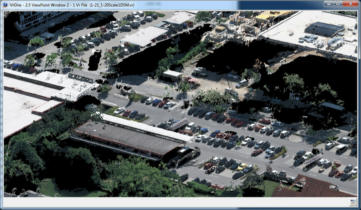
Digital Surface Model (DSM) from UltraCam UCE80 displayed in 3D VrThree
Overview
Digital Surface Models (DSM) contain information about the first surface on the ground including the topographic surface, buildings, vegetation and other objects. By comparing information about a scene from two vantage points (stereo model), three-dimensional information can be extracted.
VrDSM utilizes robust stereo matching techniques along with user defined parameters to produce accurate point cloud information.
Vr Mapping’s implementation of DSM generation performs a fully automatic production of point clouds from stereo models. The use of CPU threading processing produces tens of millions of points per minute. Full format aerial film data at full resolution takes 3-4 minutes per model and produces hundreds of millions of points.
Most digital models process in less than two minutes. Point clouds are fully compatible with stereo viewing in VrTwo (including over the original stereo models for QC), and in VrThree (VrLiDAR)’s 3D VrThree software.
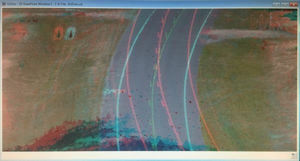

Anaglyph (red/cyan) point cloud (DSM) display in 3D VrThree
Command Reference
File
Exits VrDsm
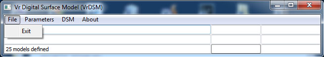
File pull down menu
Exit
Exits VrDsm. If any parameters have been changed, a dialog will be displayed allowing the recording of the DSM generation parameters.
Parameters
Defines, loads and records DSM generation parameters.
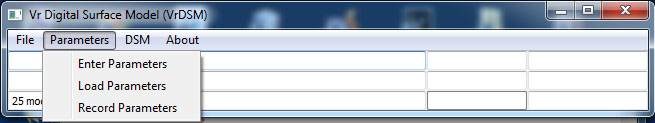
Parameter pull down menu
Enter Parameters
Allows the entry/edit of DSM generation parameters
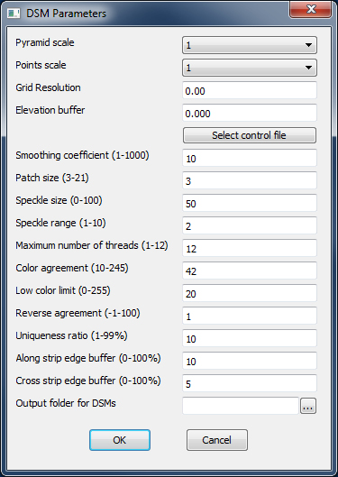
DSM parameters dialog
Pyramid scale
Pyramid scale to use for DSM extraction. The higher the scale the less points. default=1
Points scale
Pyramid scale to use for saving points. This makes it possible to get the full resolution quality and lower resolution density. default=1
Grid Resolution
Optional post processing to thin the data to an approximate grid. To disable set to zero.
Elevation buffer
A points file is used to determine the valid elevation range for extraction. The elevation range of the points that project into individual models will be extended by this buffer amount.
Select Control File
Used to define the input ground point file. This file can be a VR control file (*.cor), a bundle intersection report, a socet GPF file, or a Match AT project file. The VR bundle intersection report is the recommended format.
Smoothing coefficient (1-1000)
The higher then number, the smoother the points. default=10
Patch size (3-21)
Pixel matching patch size. Typically, an odd number between 3 and 11. default=3
Speckle size (1-100)
Maximum size of smooth disparity regions to consider their noise 'speckles' and invalidates them. A 50-200 range is typical, and a setting of 0 disables. default=50
Speckle range (1-10)
Defines the disparity difference that is considered as 'speckle' if Speckle Size is non-zero. 1 or 2 is normal. default=2
Maximum number of threads (1-n)
Limits the number of threads the DSM process uses in order to prevent the system from running out of resources. default=Maximum number of threads available
Color agreement (10-245)
Epipolar images are 8 bits per channel, and this limits how different colors between matched pixels can be. A lower value indicates a more perfect color match default=42.
Low color limit (0-255)
As the image values approach pure black matching becomes unreliable. A value to 0 will match everything while a value of 255 will match nothing. default=20
Reverse agreement (-1-100)
Matching is done left to right and right to left. The results must match with plus or minus the 'Reverse agreement'. default=1
Uniqueness ration (1-99%)
Margin in percent by which the best computed match should win the second best. default=10
Along strip edge buffer (0-100%)
Edge buffer (in percent of the epipolar image x dimension) to exclude from the DSM. default=10
Cross strip edge buffer (0-100%)
Edge buffer (in percent of the epipolar image y dimension) to exclude from the DSM. default=5
Output folder for DSMs
Defines the output folder for resulting DSMs. blank=Use same folder as the first defined .vmo file
Load Parameters
Loads previously recorded DSM parameters
Record Parameters
Records current DSM Parameters
DSM
Defines stereo input models and generates DSMs
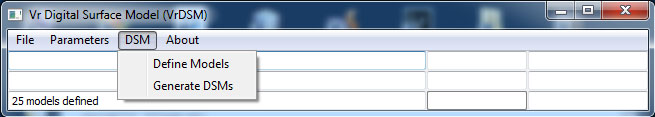
DSM pull down menu
Define Models
Allows the definition of the stereo models (.vmo) files to be used to create DSMs
Generate DSMs
Generates DSMs based on the current parameters.
About
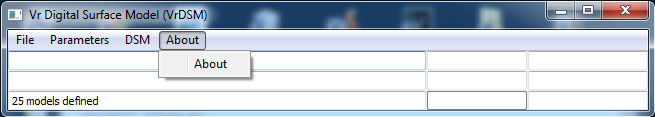
About pull down menu
About
Displays information about VrDsm including the version number.
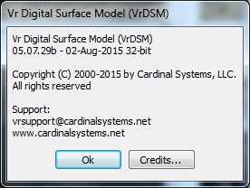
The About dialog