Vr Mapping |
ON-LINE REFERENCE DOCUMENTATION CARDINAL SYSTEMS, LLC |
Digitizer Configurations
The ALTEK/KURTA AC22 DataTab DT12/18 is a Xy digitizer and is connected to the computer via a serial interface. The serial settings are in the file: \vr\hostdir\ac22.set
Default Serial Settings File
Device=COM1
Baud=9600
CharSize=8
Parity=0
Stopbits=1
XonStus=0
XoffStus=0
The ALTEK/KURTA AC32 is a Xy digitizer and is connected to the computer via a serial interface. The serial settings are in the file: \vr\hostdir\ac32.set
Default Serial Settings File
Device=COM1
Baud=9600
CharSize=8
Parity=0
Stopbits=1
XonStus=0
XoffStus=0
The file \vr\hostdir\c9100.key contains cursor button cross-references. This file may be edited to suit you needs.
The CALCOMP 9100 is a Xy digitizer and is connected to the computer via a serial interface. The serial settings are in the file: \vr\hostdir\c9100.set
Default Serial Settings File
Device=COM1
Baud=9600
CharSize=8
Parity=0
Stopbits=1
XonStus=0
XoffStus=0
The file \vr\hostdir\c9100.key contains cursor button cross-references. This file may be edited to suit you needs.
The CALCOMP DrawingBoard is a Xy digitizer and is connected to the computer via a serial interface. The following documentation has been tested for the Drawingboard III and the Drawingboard VI.
The serial settings are in the file: \vr\hostdir\db3.set
The USB interface on the Drawingboard VI is not supported.
Default Serial Settings File
Device=COM1
Baud=9600
CharSize=8
Parity=0
Stopbits=1
XonStus=0
XoffStus=0
Tablet Settings
Following are the default settings for the tablet that match the settings in the Default Serial Settings file. There are two banks of settings with 18 settings each.
BANK SETTINGS
1 2 3 4 5 6 7 8 9 10 11 12 13 14 15 16 17 18
A 1 1 0 0 1 1 1 1 1 1 0 1 0 1 1 1 0 1
B 0 0 1 1 0 0 0 0 0 0 0 0 0 0 0 0 0 0
C 0 0 1 1 0 0 0 0 0 0 0 0 0 0 0 0 0 0 (Drawingboard VI)
See the Tablet Works CD from GTCO Calcomp for more information.
NOTE: It is not necessary to install the drivers from the Tablet Works CD. These drivers are not required for operation with VrOne.
Changing The Tablet Configuration
| • | Place cursor over the [CONFIG EXIT] box. Press any cursor button. The CONFIGURATION light should be on. |
| • | Press the desired BANK button [A 1-18] or [B 1-18] or [C 1-18]. The power light will come on to indicate that box being set. NOTE: Bank C is available on the Drawingboard VI |
| • | Move the cursor over the CONFIGURATION buttons and make changes to match the configuration above. |
| • | Place cursor over the SAVE [DEFAULT] (or [2] or [3]) box. Press any key to save the current configuration. |
| • | Place cursor over the [CONFIG EXIT] box. Press any cursor button. The CONFIGURATION light should now be off. |
The Hitachi Puma Plus is a Xy digitizer and is connected to the computer via a serial interface. The serial settings are in the file: \vr\hostdir\puma.set
Default Serial Settings File
Device=COM1
Baud=9600
CharSize=8
Parity=0
Stopbits=1
XonStus=0
XoffStus=0
The file \vr\hostdir\puma.key contains cursor button cross-references. This file may be edited to suit you needs.
Tablet Settings
Following are the default settings for the tablet that match the settings in the Default Serial Settings file.
Configuring the Tablet
You will need the PUMA PLUS/SETUP MENU and the PUMA PLUS/CUSTOM MODE MENU.
To Enter setup: Place cursor over Puma+ area on the upper right corner of the tablet frame. Hold any button 1 for 3 seconds. Press:
[CUSTOM] on top menu [HITACHI] on bottom menu
[MAX] [REMOTE] [1000] [8 bit] [None] [1 Stop] [BAUD]
[Binary] green box [No] 5 Byte Binary
[SAVE] on top menu
See the Puma Plus documentation for more information.
The Numonics 2000 series is a Xy digitizer and is connected to the computer via a serial interface. The serial settings are in the file: \vr\hostdir\numo.set
Default Serial Settings File
Device=COM1
Baud=9600
CharSize=7
Parity=0
Stopbits=1
XonStus=0
XoffStus=0
Tablet Settings
Following are the default settings for the tablet that match the settings in the Default Serial Settings file.
Configuring the Tablet
SWITCH A SWITCH B MODE SWITCH
8 7 6 5 4 3 2 1 8 7 6 5 4 3 2 1 1 2 3 4 OFF OPEN
* * * * * *
* * * * * * * * * * * * * * ON CLOSED
See the Numonics 2000 documentation for more information about the above switch settings.
The Numonics AccuGrid series is a Xy digitizer and is connected to the computer via a serial interface. The serial settings are in the file: \vr\hostdir\agrid.set
Default Serial Settings File
Device=COM1
Baud=9600
CharSize=8
Parity=0
Stopbits=1
XonStus=0
XoffStus=0
Tablet Settings
Following are the default settings for the tablet that match the settings in the Default Serial Settings file.
OUTPUT FORMAT : Numonics Binary
BAUD RATE : 9600
DATA BITS : 8
PARITY : None
STOP BITS : 1
MODES : Polled
INCREMENT SIZE : 0
STREAM RATE : MAX
LINES PER INCH : 1000
TRANSMIT OUT OF PROX : Enable
To save, press button while cursor is in CONFIRM CHANGES box
Configuring the Tablet
| • | Align AccuGrid Setup Menu with bottom edge of active area. |
| • | Place cursor on MENU box on the right side of the tablet. |
| • | Press and hold any key until continuous tone stops. |
| • | Place cursor on Menu origin on Setup Menu and press any key. |

The Numonics GridMaster is a Xy digitizer and is connected to the computer via a serial interface. The serial settings are in the file: \vr\hostdir\nugm.set
Default Serial Settings File
Device=COM1
Baud=9600
CharSize=8
Parity=0
Stopbits=1
XonStus=0
XoffStus=0
The file \vr\hostdir\nugm.key contains cursor button cross-references. This file may be edited to suit you needs.
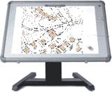
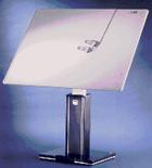
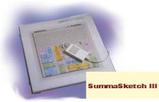 Summagraphics SummaSketch III with 16 button cursor
The Summagraphics SummaSketch III is a Xy digitizer normally 12”x12” inches in size and is connected to the computer via a serial interface. The serial settings are in the file: \vr\hostdir\ss16.set. The serial settings are not configurable on this tablet and the default values must be used.
Default Serial Settings File
Device=COM1
Baud=9600
CharSize=7
Parity=2
StopBits=2
XonStus=0
XoffStus=0
All analog instruments share similar characteristics in that they output three-dimensional square coordinates and do have the ability to be driven to a known location. Once the orientation is complete the instrument coordinates may be read and transformed to ground using the values generated by orientation. The orientation program needs to differentiate between the different types of analog instruments for accurate results but VrOne does not.
There are three interfaces that support all analog instruments. The first is the Fischer Computer Systems SEC-PC card, which is inserted into an ISA slot inside the computer. The second is the Fischer Computer Systems SEC-PCI card, which in inserted into a PCI slot inside the computer. The third is the Fischer Computer Systems SEC-232 interface that connects to one of the computers serial ports. The SEC-232 was commonly used on UNIX computers in the past. Because all analog instruments may be connected to one of these two interfaces there are only two drivers for these instruments.
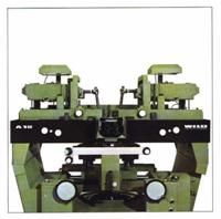
The supported analog instruments are the Wild AG1, Wild B8, Wild A10, Wild A8, Kern PG2, Zeiss E3, Zeiss TopoCart, Galileo 2C and the Galileo G6/G7/G8.
 Fischer Computer Systems SEC-PC for Analog Stereo Instruments
The Fisher Computer Systems SEC-PC card is inserted into an ISA slot inside the computer.
SEC-PC Configuration
If this is the first time this program is being run then the SEC-PC drivers must be installed. Following are instructions for installing these drivers.
The drivers may be downloaded from the Fischer Computer Systems web page at www.secpc.com
Installing SEC-PC drivers on Windows NT 4.0 and Windows 2000
| • | Install driver files in c:\secnt\ |
| • | Type: cd \secnt\install |
| • | Type: dcopy |
| • | Type: register |
| • | Reboot computer |
NOTE: register requires regini.exe, which is part of NTRESKIT in Registry Tools
After reboot is complete:
| • | Start REGEDIT |
| • | Search for SECIO (use Find on Edit pulldown) There may be several SECIO entries. Search until the one with EmulateHardware in the Parameters Folder is found. |
| • | Open Parameters folder |
| • | EmulateHardware should be set to 0 |
| • | IoPortAddress should be set to the address set on SEC-PC card as follows: (816 or 820) (See below) |
| • | Exit REGEDIT and reboot computer. |
The IoPort Address Switch Settings:
OPEN OPEN
* * * * * * *
* * * * * * * * *
1 2 3 4 5 6 7 8 1 2 3 4 5 6 7 8
816 (330 hex) 820 (334 hex)
This operation should only be done once.
The SEC-PC IO address and the Footswitch Bounce Count may be set using the VrOne configuration program.
The SEC-PC IO Address from the VrOne configuration is not used from Windows NT.
The Bounce Count parameter is used for footswitch de-bouncing in which the footswitch must stay down this many iterations to be considered a valid press. A good starting parameter is 10 to 20.
The file \vr\hostdir\secpc.key contains footswitch and keypad cross-references. If this file does not exist, the SEC-PC driver will create it.
 Fischer Computer Systems SEC-PCI for Analog Stereo Instruments
The Fisher Computer Systems SEC-PCI card is inserted into a PCI slot inside the computer. This card has been tested with VrOne in Windows 2000/XP only.
SEC-PCI Configuration
After inserting the SEC-PCI card, reboot the computer. A New Hardware Wizard dialog box should appear as follows. Insert the FCS SEC-PCI Driver Install Disk, press Next and follow instructions

The file \vr\hostdir\secpci.key contains footswitch and keypad cross-references. If this file does not exist, the SEC-PCI driver will create it.
The Vr configuration program, VrCfig, is used to configure VrOne to use this card.
The SEC-PC IO Address from the VrCfig is not used by this card.
The Bounce Count parameter in VrCfig is used for footswitch de-bouncing in which the footswitch must stay down this many iterations to be considered a valid press. A good starting parameter is 500 to 1000.
Fischer Computer Systems SEC-232 for Analog Stereo Instruments
The Fischer Computer Systems SEC-232 is an external interface that connects to one of the computers serial ports. The SEC-232 was commonly used on UNIX computers in the past.
Default Serial Settings File
Device=COM1
Baud=9600
CharSize=8
Parity=0
Stopbits=1
XonStus=0
XoffStus=0
The only value used from the Serial Settings file by the SEC-232 driver is the Baud rate.
SEC-232 Configuration
The following switch settings are on the SEC-232 motherboard. (This is the largest and bottom most board in the SEC-232.) These switch settings set the Baud rate to 9600, Idle mode to OFF and Beep mode to ON.
1 2 3 4 5 6 7 8 ON
* * * * * *
* * OFF
The following switch settings are on the SEC interface board. (This is the board that the cable from the stereo plotter is connected to). These switch settings set the SEC-PC board inside the SEC-232 to 816 (330 hexadecimal). This is an internal setting and should not need to be changed for VrOne.
1 2 3 4 5 6 7 8
* * * *
* * * *
The SEC-232 transmits data on RS-232 pin 2 and receives data on pin 3.

The Galileo Digicart-40 and StereoCart are analytical Xyz stereo digitizers and are connected to the computer via a serial interface. The serial settings are in the file: \vr\hostdir\dcart.set
Default Serial Settings File
Device=COM1
Baud=9600
CharSize=8
Parity=0
Stopbits=1
XonStus=0
XoffStus=0
The file \vr\hostdir\dcart.key contains cursor button cross-references. This file may be edited to suit you needs.
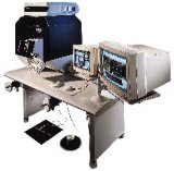
 AP32 Analytical Instrument Conversion
AP32 supports the most popular analytical plotters such as the Planicomp P-Series from Zeiss, the SD2000/SD3000 (and the upgraded DSR14) family from Leica, and the Aviolyt (AC1, BC1, BC2 and BC3), Kern DSRx and C1xx instruments, provided the AC2000/BC2000, DSR2000 and P100 Upgrade Kits from SoftMap, Inc upgrade them.
When AP32 is connected to VrOne it outputs different formats based on the type of instrument. When AP32 is interface the the SD2000/SD3000, DSRxx, Wild Aviolyt AC1/BC1/BC2 or BC3 it outputs the Leica SD2000 format. When AP32 is interfaced to the Zeiss C100/C120 or Planicomp P-Series P1/P2 or P3 it outputs Zeiss Planicomp format. VrOne may be configured for the SD2000 or Zeiss P1/P2/P3/P33 when using AP32. See Leica SD2000 or Zeiss P1/P2/P3/P33 for more information.
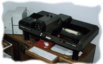
 ABC Analytical Instrument Conversion
ABC software and hardware is a package for the conversion to PC of Analytical Stereo plotters, including: Zeiss Planicomp C-100 Series, the Wild Aviolyt BC-x Series, the Kern DSRxx series, Intergraph Intermap Analytic (IMA), Traster T-x Series and Wild OR-1. The ABC conversion is connected to the computer via a serial interface. The serial settings are in the file: \vr\hostdir\abc.set
Default Serial Settings File
Device=COM1
Baud=9600
CharSize=8
Parity=0
Stopbits=1
XonStus=0
XoffStus=0
The file \vr\hostdir\abc.key contains cursor button cross-references. This file may be edited to suit you needs.
NOTE: It may be necessary to jump the CTS (Clear to Send) and DTR (Data Terminal Ready) pins of the serial cable connector on the controlling computer side. CTS is pin number 5 and DTR is pin number 20 on a 25 pin serial connector. CTS is pin number 8 and CTS is pin number 4 on a nine pin connector.
ABC IMA Conversion
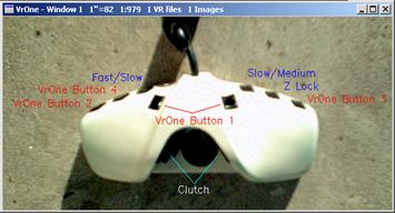
Following are the button and footswitch cross-reference information for the ABC IMA Intergraph Intermap conversion. The default VrOne and system key assignments for the puck and for the footswitch are shown below with the VrOne button assignments shown in red. Abc Conversion button assignments are shown in blue. Consult the ABC documentation for information about customizing these buttons. The button assignments for VrOne may be changed in the key file: \vr\hostdir\abc.key.

The Leica SD2000 is an analytical Xyz stereo digitizer and is connected to the computer via a serial interface. The serial settings are in the file: \vr\hostdir\sd2000.set
The SD2000 format is widely used by several manufacturers:
| • | Leica – Leica Mapping Terminal |
| • | SoftMap Inc. – AP32 Analytical conversion and model orientation |
| • | ABC Software Developers – ABC32 Analytical conversion and model orientation |
| • | Luis Cogan – MACS Multimodel |
The SD2000 format is also output when the AP32 Analytical conversion is on a Wild BC2, Wild BC3 and KERN DSR. The settings in the Serial Settings file will depend on the configuration as noted below.
Default Serial Settings File
Device=COM1
Baud=9600
CharSize=8
Parity=0
Stopbits=1
XonStus=0
XoffStus=0
HandShake=1
UseGround=0
The HandShake keyword specifies if handshaking is to be done when driving the instrument.
HandShake should be set to 1 when AP32 is connected to a Wild BC3 and set to 0 for all other configurations.
UseGround should be set to 0 when using SD2000 format and should be set to 1 when using MACS Multimodel
The file \vr\hostdir\sd2000.key contains cursor button cross-references. This file may be edited to suit you needs.
Using The Kern DSR 16 Button Keypad With AP32
The file \\DSR\\INPUTKEY.DEF must be modified so that buttons 7 and 8 are different than the left and right footswitches. This file is on the DSR controlling computer and it must have a keyboard and monitor connected to it. The DOS program EDIT may be used to edit this file.
In the file INPUTKEY.DEF
Change: KEY7 24212221
To: KEY7 20212221
Change: KEY8 24212321
To: KEY8 20212321
Key Cross-Reference
The file \vr\hostdir\sd2000.key contains cursor button cross-references. This file may be edited to suit you needs. The Raw Key is the cross-referenced key from the instrument and can be determined by running Test Digitizer in the VrOne configuration program in Configuration->Xyz Digitizers.
The following cross-reference should be used as defaults when the AP32 is connected to the Wild BC1 or Wild BC2
# SD2000 KEY CROSS-REFERENCE
#
# Filename: c:\vr\hostdir\sd2000.key
#
# Up to 16 keys can be cross-referenced to 12
# VrOne keys
# Valid VrOne keys are: 0 1 2 3 4 5 6 7 8 9 10 11
# Where 10 is the * key
# Where 11 is the # key
#
# Raw Key VrOne Key (0-11)
# | |
# v v
KEY 0 0
KEY 1 1
KEY 2 2
KEY 3 3
KEY 4 4
KEY 5 5
KEY 6 6
KEY 7 7
KEY 8 8
KEY 9 9
KEY 10 10
KEY 11 11
KEY 12 12
KEY 21 1
KEY 23 2
KEY 0 -1
The following cross-reference should be used as defaults when the AP32 is connected to the Wild BC3
# SD2000 KEY CROSS-REFERENCE
#
# Filename: c:\vr\hostdir\sd2000.key
#
# Up to 16 keys can be cross-referenced to 12
# VrOne keys
# Valid VrOne keys are: 0 1 2 3 4 5 6 7 8 9 10 11
# Where 10 is the * key
# Where 11 is the # key
#
# Raw Key VrOne Key (0-11)
# | |
# v v
KEY 0 0
KEY 1 1
KEY 2 2
KEY 3 3
KEY 4 4
KEY 5 5
KEY 6 6
KEY 7 7
KEY 8 8
KEY 9 2
KEY 10 10
KEY 11 11
KEY 12 12
KEY 21 1
KEY 23 4
KEY 9 11
It is possible to connect VrOne to a Wild BC1/BC2 that is still running on the Data General Nova 4X or the Data General DG 30. In this configuration the Data General is used for model orientation and controls the instrument real-time loop. VrOne runs on a stand-alone PC and connects to the Data General via a serial cable. An interface program called PM6V is run on the Data General, which communicates with VrOne.
NOTE: Most customers upgrade the AC1/BC1/BC2 to one of the conversion packages such as AP32 or ABC. Due to the age of the Data General computers, the connection of VrOne to these computers is becoming rare. It is suggested the instrument be upgraded.
The configuration of the VrOne serial settings in the file: \vr\hostdir\pm6.set
Default Serial Settings File
Device=COM1
Baud=9600
CharSize=8
Parity=2
Stopbits=1
XonStus=0
XoffStus=0
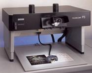

The Zeiss P1/P2/P3/P33 is an analytical Xyz stereo digitizer and is connected to the computer via a serial interface or a GPIB (General Purpose Interface Bus) interface.
Serial Interface
Most Planicomp models have both GPIB and serial interface connections on the instrument motherboards. It is important to check the availability of the serial interface before configuration. The serial settings are in the file: \vr\hostdir\p3.set. There is a nine pin connector on the mother board of the P-processor in the Zeiss instrument. Using the serial interface allows the instrument to be connected to almost any computer. The transfer rate of the serial connection is slower than the GPIB interface.
Serial Cable
The pin-out on the Zeiss instrument is non-standard is a special cable is needed. On a standard nine pin connector, pin 5 is normally the ground but the Zeiss instrument uses pin 7 for this purpose. The cable configuration is as follows:
Description |
Pin - Zeiss |
Pin - Computer |
Transmit |
2 |
2 |
Receive |
3 |
3 |
Ground |
7 |
5 |
The connector for the Zeiss instrument is a 9-pin Female connector
The connector for the application is a 9-pin Male connector. If the RS-232 port on the application computer is a 25-pin connector then a 9 to 25 pin adapter will be needed.
Configuration Of The Zeiss Instrument
The RS-232 protocol settings are set on the 517521-9110 board and are as follows:
Switch |
Switch OFF |
Switch On |
1 |
IEEE-488 |
RS-232 |
2 |
Parity Enable |
Parity Disable |
3 |
Parity Even |
Parity Odd |
4 |
2 Stopbits |
1 Stopbit |
5 |
8 Databits |
7 Databits |
Switches 6-8 set the RS-232 baud rate:
Switch |
150 |
300 |
600 |
1200 |
2400 |
4800 |
9600 |
19200 |
6 |
ON |
OFF |
ON |
OFF |
ON |
OFF |
ON |
OFF |
7 |
ON |
ON |
OFF |
OFF |
ON |
ON |
OFF |
OFF |
8 |
ON |
ON |
ON |
ON |
OFF |
OFF |
OFF |
OFF |
The default VrOne switch settings are:
19200 Baud – 8 Data Bits – No Parity – 1 Stop Bit
Switch-> |
1 |
2 |
3 |
4 |
5 |
6 |
7 |
8 |
ON |
* |
* |
|
* |
|
|
|
|
OFF |
|
|
* |
|
* |
* |
* |
* |
Configuration of VrOne
The above Zeiss instrument values must be match the settings in the VrOne Serial Settings file: \vr\hostdir\p3.set.
Default Serial Settings File
Device=COM1
Baud=19200
CharSize=8
Parity=0
Stopbits=1
XonStus=0
XoffStus=0
HandShake=1
UseGround=0
GPIB Interface
All Planicomp models have a GPIB connector on the motherboard that is used to connect the Zeiss instrument to the computer. This requires an additional interface card to be placed in the application computer. VrOne currently uses the Capitol Equipment Corporation CEC-488 card.
The CEC-488 Interface Card may be used to connect VrOne to the Zeiss P1/P1/P3 stereo plotters and is manufactured by Capitol Equipment Corporation (www.cec488.com). VrOne has been tested using the PCI version of this card running Windows 2000. Although there are installations running VrOne and Windows ME with this card, we recommend the use of Windows 2000 or Windows NT.
While most of the Zeiss instruments offer a serial interface, the CEC-488 is much faster when reading and writing coordinate data to the instrument. The CEC-488 is based on the IEEE-488 interface standard that was used by Hewlett Packard as HP-IB and by other manufacturers as GPIB (General Purpose Interface Bus).
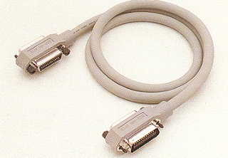
GPIB Interface Cable
The cable shown below is required to connect the Zeiss Planicomp to the application computer. This cable may be referred to as a GPIB Cable, HPIB Cable or IEEE-488 Cable.
The standard release of VrOne has the ability to interface to the Leica SOCET SET DPW (Digital Photogrammetric Workstation). This gives the ability to collect data with VrOne with capabilities that include the display of stereo vectors in SOCET SET. Use the VrOne configuration program VrCfig to set SOCET SET as the current Xyz digitizer.
Assigning 3D Mouse Buttons
Copy the SOCET button assignment file \vr\data\vrone.acc to \usr\geoset\internal_dbs\events\VRONE (Note: The filename VRONE must be upper case)
This file contains the cross-references from the 3D mouse buttons to VrOne buttons 1-12. Some of these button assignments may conflict with existing assignments delivered from LH Systems. You can remove assignments to unused applications in \usr\geoset\internal_dbs\events to make more 3D mouse buttons available.
The 3D mouse button assignments may be edited in SOCET SET by using: Preferences-> Keyboard/Trackball Accelerator Mapping
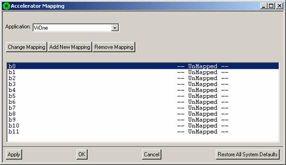
The b0-b11 listed on the left side of the Accelerator Mapping dialog box are the 12 VrOne buttons with b0 normally set to toggle snap, b10 for the * key and b11 for the # (End) key. By default the VrOne button assignments are UnMapped.
VrTwo adds stereo viewing to the VrOne editing and data capture package. VrTwo is designed to work together with VrOne and all the functionality of VrOne is available while running VrTwo. Use the VrOne configuration program VrCfig to set VrTwo as the current Xyz digitizer.