Vr Mapping |
ON-LINE REFERENCE DOCUMENTATION CARDINAL SYSTEMS, LLC |
DXF OUT (DxfOut)
Type: Translator
Translates VrOne file(s) to DXF (Drawing Exchange Format).
The DXF format is commonly used to translate map data to Autodesk’s AutoCAD program. Due to the popularity of the format, it is used by many other CADD and GIS (Geographic Information Systems) systems for the transfer of map vector data. From GIS to civil engineering systems, DXF is considered the de-facto standard for moving vector data. Experience has shown that DXF is well-suited to move vector data to the ARC INFO GIS system.
The DXF format is not without some problems when dealing with map data. While symbols and text translate very easily, three-dimensional and fonted (patterned) lines do not. These map features require some additional options.
The VrOne DXF Out translator is very flexible and offers many options for translating VrOne map data to AutoCAD.
Each symbol definition in VrOne may be translated to DXF in one of four different ways. It may be translated as a Block, exploded, placed as text, or translated as a DXF point. Symbol names may also be cross-referenced to a client’s block library and a scale factor may be applied to adjust the size.
Each VrOne line font may be translated to DXF in one of four different ways. It may be translated to a DXF line style, exploded, use a symbol line, or be translated using DXF bulges.
Because of the many options offered by DXF Out, you should communicate with your client to discuss the options and determine the best translation method to suit their needs. Time should be spent becoming familiar with the options offered and test translations should be done to AutoCAD to view the translation results. Dxf Out can translate map data using very basic translation parameters which produce lines with no line fonting, or advanced translation options which produce a readable and usable map for your client.
This documentation will point out the advantages and disadvantages to many of the translation options.
AutoCAD is a registered trademark of Autodesk Inc.
|
Available Key-ins
Key-in |
Description |
Range |
PARFIL= |
Load parameter file |
Dxf Out parameter file name (.dxo) |
HELP |
Display help |
|
RUN |
Run Dxf Out |
|
DXF Out
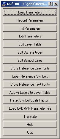
Loads previously recorded DXF Out (.dxo) parameter file.
Records current translation parameters to a DXF Out (.dxo) parameter file.
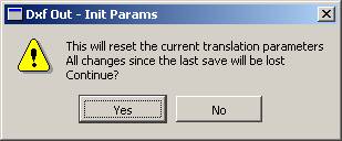
Initializes translation parameters to default values. NOTE: Current translation parameters will be lost.
Allows editing general translation parameters.
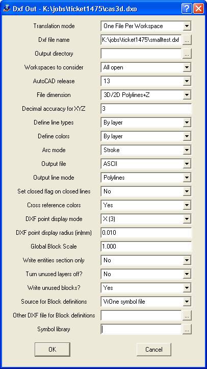
Translation Mode?
Determines how DXF files will be written.
Single File |
All entities are written to a single output file. The Dxf file name parameter must be filled in when using this option. |
One File Per Workspace |
A separate DXF file is created for each open workspace. The DXF filenames are the same as the workspace name with a .dxf extension. The Dxf file name parameter is ignored. The output directory is used to determine where the files are placed. |
One File Per Feature Code |
A separate DXF file is created for each unique feature code. All entities that have the same feature code are written to the same DXF file with the DXF file name the same as the feature code value. The output directory determines where the files are placed. |
One File Per Layer Output Name |
A separate DXF file is created for each unique layer output name in the layer cross-reference table. All entities with the same output layer name are written to the same DXF file, with the DXF file name the same as the output layer name. The output directory determines where the files are placed. |
One File Per VrOne Layer Name |
A separate DXF file is created for each unique layer name in the VrOne layer table. All entities with the same VrOne layer name (not related to the output layer) are written to the same DXF file, with the DXF file name the same as the VrOne layer name. The output directory is used to determine where the files are placed. |
Dxf file name
Defines file name to which to write DXF translated data. If this file exists, it is overwritten.
Output directory
Defines output directory to place DXF files if not using Single File translation mode. If left blank, files are placed in the same directory as the VrOne files.
Workspaces to consider
Definse workspaces to use when translating VrOne data to a DXF file. Options are “Current only” or “All open”. When “All open” is selected, all open workspaces will be translated into a single DXF file.
AutoCAD release
Defines the AutoCAD release format to use when translating. Options are 9, 10, 11, 12, and 13. Currently, AutoCAD Release 14 and AutoCAD 2000 support files written in Release 13.
File dimension
Determines the method to translate elevations to DXF. It is possible to override this option per layer by using the Layer Table cross-reference dialog. Options are:
2D |
2 dimension DXF file. |
3D |
3 dimension DXF file. Polylines are created as 3d polylines. |
3D/2D Polylines+Z |
3 dimension DXF file. Polylines are created as 2d polylines with an elevation in the header and elevations on each vertex. NOTE: AutoCAD might change the line to make the line point elevations the same. |
3D/2D Polylines+Thick |
3 dimension DXF file. Polylines are created as 2d polylines with an elevation in the header and elevations on each vertex. Elevations are placed as thickness in the polyline header and on each vertex. NOTE: AutoCAD might change the line to make the line point elevations the same. |
In some versions of AutoCAD operations such as joining lines are not allowed on 3D lines in which the elevation of the line points were not the same. The last two options are variations on the 3D option.
File accuracy for XYZ
Defines the number of places to the right of the decimal point to display for the coordinate positions written to the DXF file.
Specifies how line types will be referenced in the DXF file. Each DXF file has a layer table that defines a layer name, the layer line type and the layer color. Options are:
By layer |
If a line type is used, the line type definition is not placed with the entity and the line type definition in the layer table is used. Using this setting makes all lines using line types on a layer use the same line type definition. |
By entity |
If a line type is used, the line type definition is placed with the entity and the line type definition in the layer table is ignored when drawing the entity. This allows multiple line type definitions to be used within a layer. |
Defines how colors will be referenced in the DXF file. Each DXF file has a layer table that defines a layer name, the layer line type and the layer color. Options are:
By layer |
The color definition is not placed with the entity and the color definition in the layer table is used. Using this setting makes all entities on a layer the same color. |
By entity |
The color definition is placed with the entity and the color definition in the layer table is ignored when drawing the entity. This allows multiple colors to be used within a layer. |
Arc mode
VrOne supports lines that are defined as arcs. This parameter defines the method to translate these arcs. Options are:
Stroke |
Individual arc points are placed in the DXF file. Advantages: If the file is three-dimension, the Z dimension is represented more accurately. Disadvantages: The DXF file is larger. |
DXF Arc |
The arc is broken out of the VrOne line and translated as a DXF arc. Advantages: DXF arcs are created and may be edited by the client. Disadvantages: If the file is three- dimensional, the elevation is not represented well along the arc. |
DXF Bulge |
The arc is broken out of the VrOne line and translated as a DXF bulge. Advantages: DXF bulges are created and may be edited by the client. Disadvantages: If the file is three-dimensional, the elevation is not represented well along the arc. |
Output file
VrOne can write DXF file in ASCII (text) format or DXF binary format. The two formats are the same, though the binary format takes less disk space. If disk space is not an issue on your computer, it is suggested that the ASCII format is used.
Output line mode
Lines may be written as DXF polylines or DXF lines.
Lines |
Lines – Each VrOne line is broken into line segments and each line is written as two coordinate positions. This option is very seldom used. Advantages: Useful only if the target systems do not understand DXF polylines. Disadvantages: Requires almost twice the disk space per line. |
Polylines |
Polylines – DXF polylines are used when ever possible. This option should always be used unless the target system does not understand DXF polylines. |
It is possible to cross a VrOne symbol to a DXF point during translation. AutoCAD allows only one graphic representation for a point and this parameter defines this representation. Points are often used to translate DTM (Digital Terrain Model) XYZ points to systems that do not understand DXF blocks. Normally, the VrOne X symbol is cross-referenced to a DXF point definition 3, which is shown graphically as an X. There are twenty possible settings for the point display mode but only one is active in a DXF file. If there are no symbols cross-referenced to DXF points in “Cross-Reference Symbols” then this parameter is ignored during translation.
DXF point display radius (in|mm)
It is possible to cross a VrOne symbol to a DXF point during translation. AutoCAD allows only one graphic representation for a point and this parameter defines the display radius for the point. This parameter is entered as inches or millimeters at target scale. Points are often used to translate DTM (Digital Terrain Model) XYZ points to systems that do not understand DXF blocks. Normally the VrOne X symbol is cross-referenced to a DXF point definition 3, which is shown graphically as an X. If there are no symbols cross-referenced to DXF points in “Cross-Reference Symbols” then this parameter is ignored during translation.
Global Block Scale
Defines the scale factor that applies to all symbols that have a cross-reference scale factor of -1.0. This allows a translation to be made where all blocks in the DXF have a uniform scale factor regardless of the symbol sizes in VrOne.
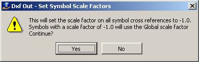
NOTE: The Reset Symbol Scale Factors can be used to quickly set all symbols cross-references to use a scale factor of –1.0.
Write entities Section only
If set to "Yes", only the entities section of the DXF will be written. This eliminates all header information such as Layer tables, Linestyle tables, and Block definitions from the DXF files. This can be useful in some versions of AutoCAD where an existing drawing can be used when importing a DXF file. In this situation, all of the existing block definitions and layer table settings in the current AutoCAD drawing remain intact.
Turn unused layers off
Each DXF file has a layer table that defines a layer name, the layer line type, and the layer color. If this parameter is set to "Yes", only layers that are used in the VrOne file(s) are placed in the layer table. Since VrOne allows 10,001 layers, if this parameter is set to no then 10,001 entries will be placed in the DXF layer table.
Write unused blocks
Each DXF file has a block table that defines all of the blocks that will be used in the drawing. If this parameter is set to "No", only blocks that are used in the DXF file(s) will be placed in the block table. If set to Yes, then all blocks defined in the current Symbol file will be written to the block table, regardless of whether they are used or not.
Source for block definitions
Normally, the DXF Out translator reads a VrOne symbol file and creates DXF blocks to represent symbols. There may be times where the client has defined their own block library and wishes you to cross-reference the VrOne symbols to their blocks. Options are:
VrOne symbol file |
VrOne symbol definitions are read and DXF blocks are created. |
Other DXF file |
The blocks from another DXF file are copied to the DXF file being created by this translator. |
Notes on using “Other DXF file”:
| • | The “Cross-Reference Symbols” menu allows the cross-referencing of VrOne symbol names to DXF block names and the application of scale factors when referencing DXF blocks. |
| • | Care must be taken to cross-reference VrOne symbol names to the block names in the DXF file. If a VrOne symbol is used and does not have a matching block name in the DXF file then an “un-referenced block name” error will occur during translation from DXF to AutoCAD. |
| • | Since DXF blocks may be created with a scale it may be necessary to apply a scale factor to VrOne symbols. |
| • | If your client has supplied you with an AutoCAD drawing (.dwg) file, you must convert it to a DXF file in order to copy the blocks. When converting this file to a DXF file, use the earliest release available, which is normally R13. |
Other DXF file for Block definitions
Defines the DXF file that contains the block definitions to copy to the current DXF file iff the “Source for block definitions” is set to “Other DXF file”. The […] browse button may be pressed in this field, which allows browsing for the target DXF file.
Symbol library
Allows an alternate symbol library to be used during the translation. If this is left blank then the currently attached symbol library will be used. If a VrOne symbol library is specified, the symbol definitions from the specified library are used during the translation.
AutoCAD uses a layer table which defines layer names. Within each layer, a line type, color, and display status (on/off) are stored. The VrOne DXF Out translator creates this table and places it in each DXF file created.
VrOne uses layer numbers and has 10,001 predefined layers. AutoCAD uses layer names. Each layer name may be up to 32 characters in length. It is possible to name layers in VrOne, but the names are only for reference and VrOne references all layers by number.
An easy way to define this table is supplied by using the “Add VrOne Layers to Layer Table” option. This scans the current VrOne file(s) and creates a layer table entry for each layer used. NOTE: If layer names have been defined in VrOne, those layer names will be used in the table. If a layer name has not been defined in VrOne then the layer number will be used with the word “Layer” before the number.
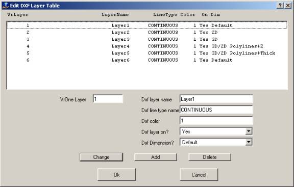
The Edit DXF Layer Table dialog box allows editing the DXF layer table. If “Define line types” is set to “By entity” in Edit Parameters then the Line Type definition in this table is ignored and may be left CONTINUOUS. If “Define colors” is set to “By entity” in Edit Parameters, the Color definition in the table is ignored and may be set to 1. All layers should be tuned on. The layer table may also be edited in AutoCAD.
VrOne Layer
Specifies the VrOne input layer.
Dxf layer name
Specifies the DXF layer name used for entities in the current VrOne Layer.
Dxf line type name
Specifies the DXF line type name used for entities in the current VrOne Layer.
Dxf color
Specifies the DXF color used for entities in the current VrOne Layer.
Dxf layer on
Specifies whether the current VrOne Layer is translated.
Dxf dimension
Determines the method to translate elevations to DXF for the current VrOne layer. Options are:
Default |
Uses whatever value is specified in the main parameters dialog. |
2D |
2 dimension DXF file. |
3D |
3 dimension DXF file. Polylines are created as 3d polylines. |
3D/2D Polylines+Z |
3 dimension DXF file. Polylines are created as 2d polylines with an elevation in the header and elevations on each vertex. NOTE: AutoCAD might change the line to make the line point elevations the same. |
3D/2D Polylines+Thick |
3 dimension DXF file. Polylines are created as 2d polylines with an elevation in the header and elevations on each vertex. Elevations are placed as thickness in the polyline header and on each vertex. NOTE: AutoCAD might change the line to make the line point elevations the same. |
In some versions of AutoCAD, operations such as joining lines are not allowed on 3D lines in which the elevation of the line points are not the same. The last two options are variations on the 3D option.
If any VrOne line fonts are to be cross-referenced to DXF line styles, this dialog may be used to create DXF line styles. By definition, DXF line styles consist of dashes, but are useful when defining VrOne line fonts that are dashed lines. Up to 60 line styles may be defined. Advantages: DXF lines styles allow the client to edit lines and make the map more readable. Disadvantages: If line points are closer than the line style distance then the line may be drawn as solid in AutoCAD.
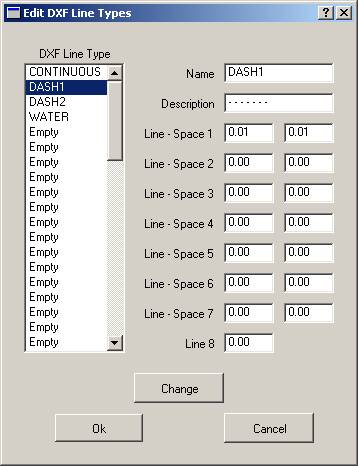
In the above dialog box only the CONTINUOUS line style is defined and represents a solid line. The line styles defined here may be cross-referenced to VrOne line fonts in “Cross-Reference Line Fonts”.
While not a feature of AutoCAD or VrOne, it is possible to create special line types called symbol lines. A symbol line is a line with DXF blocks placed at user-defined intervals along the line. Symbol lines offer mapping symbolization and give the client editing capability in AutoCAD. After a symbol line has been created, it may be cross-referenced to a VrOne line font in “Cross-Reference Line Fonts”.
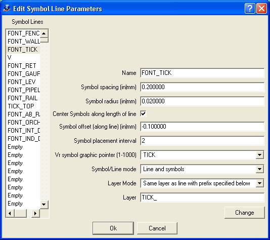
Symbol Lines
Displays the current symbol lines that have been defined. An entry of Empty means the symbol line has not been defined. Clicking an entry will copy the settings to the edit fields where they may be changed.
Name
Defines the name of the symbol line. This name will be available in “Cross-Reference Line Fonts”.
Symbol spacing (in|mm)
Defines in inches or millimeters at target scale the distance to place the symbols along a line.
Symbol radius (in|mm)
Defines in inches or millimeters at target scale the size of the symbols that are placed along the line.
Center Symbols along length of line
Specifies whether the placement of symbols is adjusted so the first and last symbols placed are equal distances from the begin and end of the line. This is useful to line a symbol up on a dashed line type, as AutoCAD displays line types using this method.
Symbol offset (along line) (in|mm)
Defines in inches or millimeters at target scale the amount which each symbol is offset along the direction of the line. A negative number offsets in the reverse direction of the line.
Symbol placement interval
Defines interval to place symbols. Use 1 to place a symbol at the spacing defined. Use a value of 2 to place a symbol at every other location, and so on. This is useful when using the center option to align symbols to dashed AutoCAD line types. In this case, the Symbol spacing must match the dash-space length of the line type to compute the alignment correctly, but you may not want symbols plotted as frequently as the line type is defined.
Vr symbol graphic pointer (1-1000)
Specifies the VrOne symbol to place along the line.
Symbol/Line mode
Specifies the symbol/line placement mode. Options are:
Off |
Do not place symbol/line. |
Line and Symbols |
Place both the line and the symbols. |
Symbols only |
Place symbols but not the line. |
Layer mode
Determines the layer in which the symbols are placed. Options are:
Same layer as line |
The symbols are placed on the same layer as the line to which they belong. |
Use symbol line name |
The symbols are placed on a layer name that matches the name of the symbol line. |
Use layer specified below |
The symbols are placed on the layer name entered in the text box below. |
Same layer as line with prefix specified below |
The symbols are placed on a new layer that combines the prefix entered in the text box with the layer the line is on. |
Same layer as line with postfix specified below |
The symbols are placed on a new layer that combines the postfix entered in the text box with the layer the line is on. |
Layer
Defines the layer name to be used according to the Layer mode setting.
Defines the settings for the cross-referencing of VrOne line fonts to DXF. Each VrOne line font may be translated to DXF in one of four different ways. It may be translated to a DXF line style, exploded, use a symbol line, or be translated using DXF bulges.
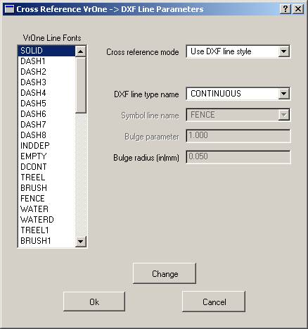
VrOne Line Fonts
Displays the VrOne line font names for the current VrOne symbol file. Clicking an entry will copy the settings to the edit fields where they may be changed.
Cross-reference mode
Defines the cross-reference mode for the currently selected VrOne line font. Options that are not valid for a cross-reference mode will be dimmed. Options are:
Use DXF line style |
Use a line style defined in “Edit DXF line types”. Advantages: Uses standard AutoCAD line type and is editable by the client. Disadvantages: Cannot define lines such as fence lines. |
Explode line font |
Breaks the fonted line into individual line segments. Advantages: Graphically, lines appear in AutoCAD the same as they appear in VrOne. Disadvantages: Since the lines are broken into segments, the file size is much larger. Due to the line segments it is very difficult for the client to edit the line as a single entity. |
Use symbol line |
Places a line with symbols. The symbols are placed at user-defined intervals. Advantages: Lines are readable as mapping features. Disadvantages: It takes many entities to create a line, which makes editing difficult. |
Use bulge |
Places a line with DXF bulges. Advantages: Makes nice tree lines. Disadvantages: Has no other use than tree lines. Requires large amount of storage. |
DXF line type name
It the “Cross-reference mode” is set to “Use DXF line style”, a line style may be selected here. Line styles may be created using “Edit DXF line types”.
Symbol line name
If “Cross-reference mode” is set to “Use symbol line”, a symbol line may be selected here. Line styles may be created using “Edit symbol lines”.
Bulge parameter
If “Cross-reference mode” is set to “Use bulge”, the bulge parameter, which defines the degree of arc, is defined here.
Bulge radius (in|mm)
If “Cross-reference mode” is set to “Use bulge”, the bulge radius is defined here in inches or millimeters.
Defines the settings for the cross-referencing of VrOne symbols to DXF. Each symbol definition in VrOne may be translated to DXF in one of four different ways. It may be translated as a Block, exploded, placed as text, or translated as a DXF point. Symbol names may also be cross-referenced to a client’s block library, where a scale factor may be applied to adjust the size.
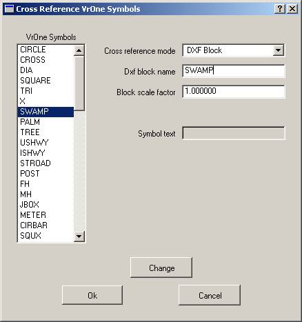
VrOne Symbols
Displays the VrOne symbol names for the current VrOne symbol file. Clicking an entry will copy the settings to the edit fields where they may be changed.
Cross-reference mode
Defines the cross-reference mode for the currently selected VrOne symbol. Options that are not valid for a cross-reference mode will be dimmed. Options are:
DXF Block |
Places the symbol as a DXF block. This is the preferred method for translating symbols |
Explode VrOne Symbol |
Breaks the symbol into individual line segments. Disadvantages: Since the symbol is broken into segments, the file size is much larger. Due to the line segments, it is very difficult for the client to edit the symbol as a single entity. |
Place text |
Places the symbol as a text label. This is normally only used when the target systems does not understand blocks. |
DXF point |
Places the symbol as a DXF point. (See DXF point display mode) |
DXF block name
It is possible to rename the VrOne symbol when translating to a DXF block. This is normally used when using a client’s block library.
Block scale factor
This scale factor is applied to the block size when translating a VrOne symbol to a DXF block. It is normally used when using a client’s block library and scaling is needed to place the block at the same size.
Symbol text
Defines text to be placed instead of a symbol if the “Cross-reference mode” is set to “Place text”. The size of the text will be the radius of the symbol.
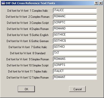
VrOne supports 12 text fonts. These font styles are cross-referenced to match the text font styles in AutoCAD. By default, this cross-reference is set to the best match between VrOne and AutoCAD text font styles and should not need to be modified.
Scans open VrOne file(s) and copies the layers used to the DXF layer table. “Edit Layer Table” may be used to cross-reference VrOne layer numbers to AutoCAD layer names. If layer names have been defined in VrOne, those layer names are used in the table. If a layer name has not been defined in VrOne, the layer number are used with the word “Layer” before the number.
Resets all scale factors to –1.0 in the Symbol Cross-Reference table. This is useful if the Global Scale Factor is used to set a uniform scale for all symbols. The following prompt is displayed after pressing this button.
Load CADMAP Parameter File
Loads a CADMAP parameter file (.ACO) and translates it into the current translation parameters.
Translates the current VrOne file(s) using the current translation parameters into a DXF file.
Help
Starts the browser and displays the current help document.
Quit
Quits Dxf Out and gives an option to save the current parameters.
The following may be done to translate VrOne file(s) to a DXF file in the fewest possible steps. The result is a translation in which all lines are translated as solid. Symbols are translated as blocks and text labels are translated with the proper text font styles.
| 2. | Define the “Dxf file name” in “Edit Parameters” |
| • | Speak to your client about the available features to best translate data to their system. |
| • | Learn about the various options for translating symbols and line fonts. |
| • | Test different options by translating files into AutoCAD. |