Vr Mapping |
ON-LINE REFERENCE DOCUMENTATION CARDINAL SYSTEMS, LLC |
Grid Line (GriLin)
Type: Interactive/Batch Application
Grids existing line(s).
Detailed Description
Grids existing line(s) by placing points on line or placing symbols along the line grid points. Points may be placed by linear distance from the start of the line or in distance in X or Y in the coordinate system. Original points on the lines may be deleted (except for the first and last points) or may be left unchanged when gridding the line(s).
Options for the assignment of elevations for the line points or symbols include:
| • | The interpolation of the elevation based on the points before and after each new point (when inserting line points) |
| • | The use of the current Z Source |
| • | The draping of the line points or symbols onto a point cloud (LiDAR) with the use of the High/Low Point Search feature. |
An optional Duplicate Point Distance may be set to keep new points from being placed too close to existing line points. Lines may also be gridded based on a user defined baseline. See Grid From Baseline for more information.
Grid line may be run interactively on single lines identified by the user or may be run in layer mode in which the lines in a user defined layer or layer(s) are gridded.
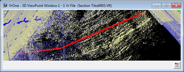
Line before gridding
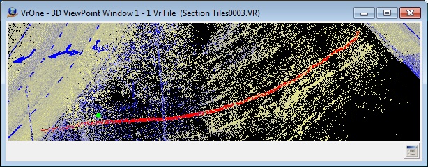
Line after gridding with High/Low Z interpolation option
Button Assignments
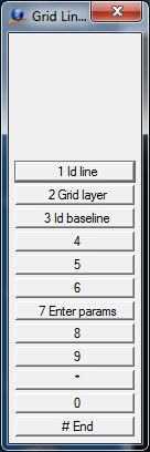
Grid Line Menu Keys
|
Button |
Description |
1 |
Id Line |
Interactive mode - Identifies a single line to be gridded. |
2 |
Grid layer |
Interactive batch mode - Allows Grid Line to be run on a layer or group of layers. (see Parameters) |
3 |
Id baseline |
Identifies a baseline to be used if the Grid Mode is set to "Grid from baseline" (see Grid From Baseline for more information) |
4 |
||
5 |
||
6 |
|
|
7 |
Enter params |
Enter/edit Grid Line parameters (see Parameters) |
8 |
||
9 |
||
* |
|
|
0 |
|
|
# |
End |
Ends application |
Parameters
The following parameters are used when gridding line in interactive and batch modes (layer mode). Pressing button 7 allows the entry of these parameters.
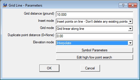
Grid distance
Defines the gridding distance. This parameter is entered in ground units.
Insert mode
Defines the action to be taken on the existing line points.
Insert points on line - Don’t delete any existing points |
The original points on the line are left unmodified |
Insert points on line - Delete original points except end points |
Original points on the line are deleted except the first and last point |
Insert points on line - Delete all original points |
All original points are deleted. The only points left on the line are the points inserted by this application. |
Insert symbols on line |
Inserts symbols on the line grid points |
Insert symbols on line and line endpoints |
Inserts symbols on the line grid points and on the line endpoints |
Grid mode
Defines the point insertion mode.
Grid linear along line |
Points are inserted linearly along the line starting from the first point on the line |
Grid on coordinate system X |
Points are inserted on the coordinate system X |
Grid on coordinate system Y |
Points are inserted on the coordinate system Y |
Grid linear along each line segment |
Points are inserted linearly along each line segment starting at the beginning of each line segment |
Grid from baseline |
Uses a user defined baseline to compute grid points |
Duplicate point distance (0=none)
Duplicate Distance. New points that are within this distance of an existing line point will be considered duplicate and will not be placed on the line. This parameter is entered in ground units. A value of zero disables the use of this parameter when inserting points on the line.
Elevation mode
The Elevation Mode determines the method of interpolating the elevation of new line points or symbols that are created.
Interpolate |
Interpolate elevation from the point before and after the new point |
Use Z source |
Interpolate elevation from existing points if Z Source is not set to Active Surface. Interpolate from active surface if Z Source is set to Active Surface. See Z Source for more information. |
Use High/Low search |
Use the current High/Low settings to set the elevation and (or) the xy coordinates. See High/Low Point Search for more information. |
The following parameters are used when gridding lines in a layer or layers. This menu is displayed when the "Grid layer" (button 2) is pressed. Gridding the lines in a layer or a group of layers is running Grid Lines in the interactive/batch or layer mode.
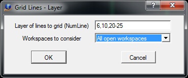
Grid Layer dialog
Layer of lines to grid
Defines the layers to search when gridding lines. A number line may be entered here.
Workspaces to consider
The current workspace or all open workspaces may be searched when gridding lines.
NOTE: Lines in layers that are turned off will not be considered even if they are specified.
Local Commands
The Grid Line parameters may be set using key-ins. This allows macros to set parameters and run Grid Line in layer mode.
Key-in |
Description |
Range |
GRIDIS= |
Defines the gridding distance |
Real number - Ground units |
INSMOD= |
Defines the action to be taken on the existing line points |
0 = Insert points on line - Don’t delete any existing points 1 = Insert points on line - Delete original points except end points 2 = Insert points on line - Delete all original points 3 = Insert symbols on line points 4 = Insert symbols on line points and on line endpoints |
GRIMOD= |
0 = Grid linear along line 1 = Grid on coordinate system X 2 = Grid on coordinate system Y 3 = Points are inserted linearly along each line segment 4 = Grid from user defined base line |
|
DUPDIS= |
Duplicate point distance. New points that are within this distance of an existing line point will be considered duplicate and will not be placed on the line. |
Real number - Ground units |
ELEMOD= |
Elevation mode. |
0=Interpolate 1=Use Z Source 2=Use High/Low search |
LAY= |
Layers to search for lines to grid when running in layer mode. |
Number line |
WSTC= |
Workspaces to consider when running in layer mode. |
0=Current 1=All |
RUN |
Run Grid Lines in layer mode |
Symbol Parameters
Key-in |
Description |
Range |
LAY= |
Layer number |
1-10001 |
GRP= |
Graphic pointer |
1-60 |
PEN= |
Pen number |
1-256 |
CON= |
Construction flag |
0-1 |
NGR= |
Non graphic pointer |
32 bit |
LNK= |
Link number |
32 bit |
FC= |
Feature code |
48 characters |
RAD= |
Symbol radius |
Inches | Mm |
ROT= |
Symbol rotation |
0-360 degrees |
High/Low Search Parameters
Please see High/Low Point Search for the setting of the High/Low search parameters using key-ins.
Intersection lines are projected perpendicular to the base lines at user defined intervals to intersect the lines to be gridded. After a base line has been identified, each line to be gridded is then identified. The three examples show the gridding from a baseline process.
The "Grid mode" must be set to "Grid from baseline" to grid from a baseline. The baseline is identified using "Id baseline" (button 3). A new baseline may be identified at any time. The example graphics window below shows the baseline as the green line and the lines to be gridded as the red lines.
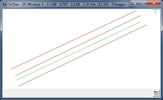
Baseline (green) and lines to be gridded from the baseline (red)
After a baseline has been identified, each line to be gridded is identified using "Id line" (button 1). In the graphics window example below, the projected lines from the base line are shown in cyan. The spacing of the projected lines along the baseline is determined by the "Grid distance" parameter. The projection lines are show here as an example but are not shown when running Grid Line.
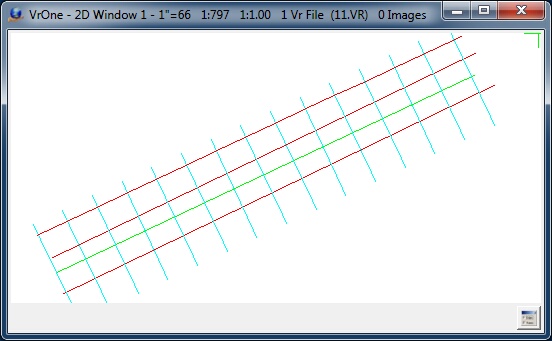
Projection lines (cyan) are show computed from the baseline
The resulting grid points are shown in the graphics window example below as crosses. The "Grid distance", "Insert mode", "Duplicate point distance", and "Elevation mode" settings are used when placing the intersecting points on the lines that are gridded. The line points may be shown in VrOne by checking "Display line points?" under Environment -> Set Display Parameters or with the Set Display (SetDis) command.
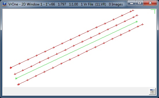
Resulting grid points (red crosses)
Grid from baseline was added in version 05.07.29t - April 2016