Vr Mapping |
ON-LINE REFERENCE DOCUMENTATION CARDINAL SYSTEMS, LLC |
Insert Cross Sections (InsCro)
Type: Interactive Application
Creates cross section lines from LiDAR surface data and allows viewing the cross section line profiles. New lines may be digitized or existing lines may be selected. Existing lines may be draped to the surface or displayed as they exist without draping. There are options to automatically add points at breaks in the surface.
Once a cross section line has been digitized or selected, it is displayed in a 3D viewing window with optional stereo capabilities. Multiple passes may be taken on each cross section line using different point filter options. All passes will be displayed in the cross section viewing window.
A typical workflow for using Insert Cross Sections to place new cross section lines is as follows:
| 1. | Start VrOne and open a .vr file containing VrPoints. |
| 2. | Start Insert Cross Sections application. |
| 3. | Select "Enter params" and make sure draping parameters are correct and passes are set up. |
| 4. | Digitize a two point line across the area where you would like a cross section line recorded. |
| 5. | Cross section view window is displayed. The pass companion window enables Save buttons for each pass processed. |
| 6. | Examine the cross section(s) in the view window and determine which one you would like to save. Use the mouse wheel to zoom in and out. The cursor will track the cross section line and points by default, press the Del key to toggle tracking off. |
| 7. | When you are ready to save the cross section line to the workspace, press the Save button next to the pass you would like to record. |
This application may also be used as a quick cross section viewing tool by using the above steps, but skipping the last one where the cross section is saved. You may continue to work in the main VrOne window while the cross section is displayed, and the cross section view cursor will follow your movements in the main graphics window.
Local Commands
Key-in |
Description |
Range |
LAY?= |
Layer number |
1-10001. ? = Pass (1-5) |
MOD?= |
Mode |
1=Line 2=Spline. ? = Pass (1-5) |
GRP?= |
Graphic pointer |
1-60. ? = Pass (1-5) |
WID?= |
Line width |
0-255. ? = Pass (1-5) |
PEN?= |
Pen number |
1-256. ? = Pass (1-5) |
CON?= |
Construction flag |
0-1. ? = Pass (1-5) |
NGR?= |
Non graphic pointer |
32 bit. ? = Pass (1-5) |
LNK?= |
Link number |
32 . ? = Pass (1-5) |
FC?= |
Feature code |
15 char. ? = Pass (1-5) |
FKEY?=name |
Changes to function key parameters |
Function key name. ? = Pass (1-5) |
Z= |
Set active Z |
|
DIG= |
Digitize a point |
|
Button Assignments
Ins Cross Sections - Main
Button |
Description |
1 Digitize pt |
Digitizes a single XYZ location. |
2 Id line |
Switches to Id line mode. |
3 Backup |
Deletes the last point on the current line. |
4 End |
Ends and saves the current line. |
5 Rescan |
Rescans the last digitized or selected line using latest parameters. |
6 |
|
7 Enter params |
Allows the setting of parameters. |
8 |
|
9 Reset display |
Returns the cross section view display to the default orientation. |
* Menu board |
Makes selection from Menu Board. |
0 Toggle snap |
Toggles snapping on / off. |
# End |
Ends application. |
Ins Cross Sections – Id line
Button |
Description |
1 Id line |
Allows selection of an existing line. |
2 Dig line |
Switch to digitize line mode (Main menu). |
3 |
|
4 |
|
5 Rescan |
Rescans the last digitized or selected line using latest parameters. |
6 |
|
7 Enter Params |
Allows the setting of parameters. |
8 |
|
9 Reset display |
Returns the cross section view display to the default orientation. |
* Menu board |
Makes selection from Menu Board. |
0 |
|
# End |
Ends application. |
Set the parameters for each pass. Passes are used to display multiple versions of the same cross section line draped to different sets of points The following dialog is displayed when this button is selected:
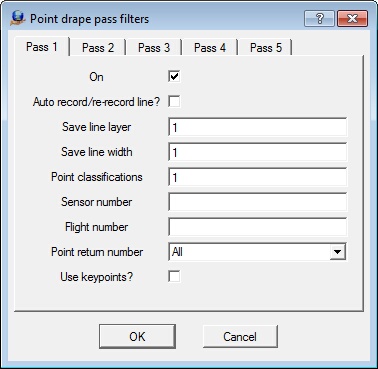
Up to five passes may be taken on the cross section line. Each pass may use filters to define a unique set of VrPoints. This allows for quick comparison of profiles between different data sets.
Pass Parameters
Unless otherwise noted, any empty pass parameter behaves as a wildcard.
On
Determines if this pass is used. Only passes that are on are processed and displayed in the view window.
Auto record/re-record line
If on, this pass will be automatically saved
Save line layer
Specifies layer to which to save cross section line. -1=Same as identified line, or xx if line is digitized. (where xx = Pass number)
Save line width
Specifies width to assign to cross section line. -1=Same as identified line, or 1 if line is digitized.
Point classifications
Defines point classifications. A number line may be used. Point classification range: 0-31
Sensor number
Specifies sensor number. number line may be used. Point classification range: 0-31
Flight number
Specifies flight number. A number line may be used. Point classification range: 0-31
Point return number
Specifies point return number. Select a point return number from 1-5 or All.
Use keypoints?
Specifies whether only keypoints should be used.
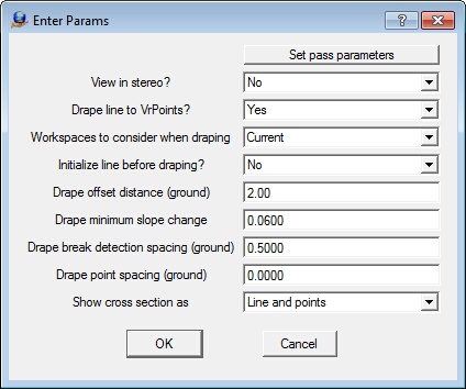
View in stereo
Yes = Displays the cross section view window in stereo mode.
No = Displays the cross section view window in standard mode.
Drape line to VrPoints
Yes = Line is draped to VrPoints
No = Line is not draped. It is assumed that the line has already been draped or follows the surface.
Workspaces to consider when draping
Current = Only uses points in current workspace.
All open = Uses points from all open workspaces.
Initialize line before draping
Yes = All points except the line end points are removed before draping the line.
No = Existing points on line will remain
Drape offset distance (ground)
Defines in ground units the distance from the left and right of the cross section line to search for points to use to define the cross section.
Drape minimum slope change
Defines the minimum slope change for break detection when draping to VrPoints. Surface slopes range from 0.0 to 1.0. 0.0 is a flat line and 0.5 is a 45 degree slope.
Drape break detection spacing (ground)
Defines in ground units the search spacing when detecting breaks in surface.
Drape point spacing (ground)
Sets in ground units the point spacing when draping to VrPoints. 0=No set point spacing - Use slope change and insert points at surface breaks.
Show cross section as
Default viewing mode of cross section line.
Lines = Only shows cross section line.
Points = Only shows points along section line
Line and points = Shows points and cross section line
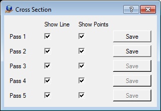
The cross section viewer window is used to display the cross section profile. The viewer has many options to control how the cross section profile is displayed. A companion window is used to control the display of each pass and to allow the cross section lines from each pass to be saved. Passes are used to display multiple versions of the same cross section line draped to different sets of points.
Below is the main cross section view with a cross section line and points displayed and the companion pass control dialog. Two passes have been taken and the lines are ready to be saved.
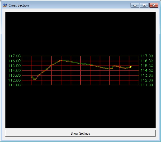
The display settings are altered by pressing the Show Settings button. To configure settings outside the Insert Cross Sections application you may use the Configure Cross Sections (ConCro) application .
Show Settings Parameters

Show xsec line
Specifies whether to show the cross section line.
Show points
Specifies whether to show the VrPoints used when draping cross section line.
Show grid
Specifies whether to show grid lines.
Show border
Specifies whether to show the border around grid.
Show stations
Specifies whether to show station labels.
Show station title
Specifies whether to show the station title.
Show elevations
Specifies whether to show elevation labels.
Show elevation ticks
Specifies whether to show elevation ticks on border.
Left offset
Defines the offset distance to left of cross section center for display of grid lines.
Right offset
Defines the offset distance to right of cross section center for display of grid lines.
Elevation height
Defines the height of grid if displaying elevations labels or grid lines.
Target scale (1=)
Defines the target scale used to determine size of labels.
Vertical grid spacing
Defines in ground units the spacing of vertical grid lines.
Horizontal grid spacing
Defines in ground units the spacing of horizontal grid lines.
Vertical exaggeration
Specifies a multiplier to apply to exaggerate the elevation of the cross section data.
Station label size (in|mm)
Defines the station label size in inches/millimeters. Target scale will be applied to compute final size.
Elevation label size (in|mm)
Defines the elevation label size in inches/millimeters. Target scale will be applied to compute final size.
Station title size (in|mm)
Defines the station title size in inches/millimeters. Target scale will be applied to compute final size.
Line width
Defines the default width to display cross section lines.
Grid layer
Specifies the layer from which to take the color used for displaying the grid lines.
Border layer
Specifies the layer from which to take the color used for displaying the border line.
Elev Label layer
Specifies the layer from which to take the color used for displaying the elevation labels.
Station Label layer
Specifies the layer from which to take the color used for displaying the station labels.
Tick layer
Specifies the layer from which to take the color used for displaying the tick lines.