Vr Mapping |
ON-LINE REFERENCE DOCUMENTATION CARDINAL SYSTEMS, LLC |
Manage DTMs (ManDtm)
Type: System Management
Allows user to manage DTM surfaces and compute surface volumes.
Detailed Description
The DTM Manager dialog displays a list of the 8 possible DTM surfaces that may be used in VrOne. Quickly set the active surface, change the parameters for a surface, or compute the DTM for a surface. If using the VrVolumes module, then the dialog also adds the ability to compute volumes between surfaces or between a surface and a flat plane.
DTM Manager Dialog
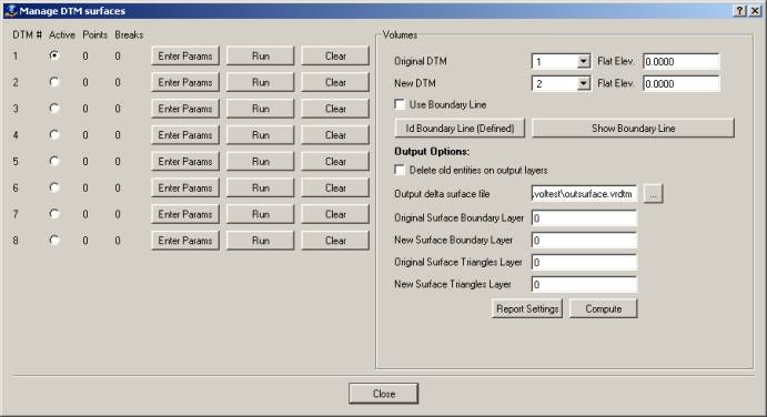
The Manage DTM Surfaces dialog box with VrVolumes enabled. Only the left half of the dialog is displayed if VrVolumes is not available.
Each surface is represented by a row in the dialog box.
Surface List
Following is an explanation of each column in the surface list. (The left side of the dialog box.)
Active
Indicates if this surface is active. Only one surface may be active at a time. The user may select the radio button to make the surface active. The ADT command may be also be used to make a surface active.
Points
Displays the number of points making up this surface. Only displayed if the Run command has been used on this surface and free DTM was set to no.
Breaks
Displays the number of break lines making up this surface. Only displayed if the Run command has been used on this surface and free DTM was set to no.
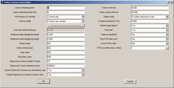
Enter Params
Makes the surface active and displays the parameters dialog box for this surface. Each surface can have its own unique set of parameters.
Run
Makes the surface active and computes the DTM based on the parameters for this surface. This is the same as using the ADT command followed by RUNDTM.
Clear
Clears the surface. Removes the surface from memory but does not affect any surface data in the VrOne file.
Enter Params
Displays the parameters dialog box for this surface. Each surface maintains its own unique set of parameters. See the documentation for SetDtm for a full explanation of the DTM parameters.
Volumes
The volumes section (the right side) of the dialog is displayed if using the VrVolumes module. VrVolumes provides cut and fill results using a prismoidal volume computation method. Volumes are calculated directly from the triangles of the surfaces.
To compute the volume between two surfaces, first define the surfaces by using the “Enter Params” button on two of the 8 available surfaces. Once the surface parameters have been defined (points and break line layers), set the Original and New DTM numbers to the appropriate surface numbers, then press the Compute button to start the volume computation process.
To compute the volume between a surface and a flat plane, at least one surface must be defined in one the 8 available surfaces. Once the surface is defined, set the Original or New surface to the appropriate surface number, and set the other surface to use the “Flat Elev”. Press the Compute button to start the volume computation process.
When computing surface to surface volumes, only the overlapping area between the two surfaces is used in the volume computations. Because this overlapping area is not always well defined, it is recommended to provide a specific boundary line for the area to be computed. To do this, use the “ID Boundary Line” button to select a boundary line before starting the volume computation. The “Use Boundary Line” option must also be turned on. This line does not need to be part of either surface, and does not need to have valid elevations. It will be integrated into each surface temporarily during the volume calculations.
During the volume computations, temporary surfaces are created that represent the merging of the two original surfaces and trimming to the boundary line area if one is specified. In order to verify and visualize the data used for volume computations, the boundary line and triangles from the merged surfaces can be saved in the VrOne file. The layers for saving this data are defined under the Output Options section.
After volume computations are complete, the results are displayed as raw Cut and Fill quantities below the compute button. These are displayed in the units of the VrOne file. For example, if working in feet, then the results will be cubic ft. Divide by 27 to get cubic yards.
Original DTM
Specifies the surface number that represents the original surface. If using a flat elevation for the original surface, then select “Flat Elev”, and enter the desired elevation in the adjacent text box.
New DTM
Specifies the surface number that represents the new surface. If using a flat elevation for the new surface, then select “Flat Elev”, and enter the desired elevation in the adjacent text box.
Use Boundary
If this is turned on, then the volume computation will be limited to an area defined by a closed boundary area. This area is defined by selecting a VrOne line using the “Id Boundary Line” button.
Id Boundary Line
This button allows the selection of an existing VrOne line to be used as the boundary of the volume computations.
Show Boundary Line
Helps identify if the correct boundary is being used for the computations. Clicking on this button will result in a white line being displayed in the VrOne graphics window, representing the outline of the currently defined boundary area.
Delete Output Layers
If this is on, then all output layers will be deleted each time volumes are computed. The output layers include the Original boundary line layer, New boundary line layer, Original Triangles layer, and New Triangles layer.
Output delta surface file
If a filename is specified, then the delta TIN is written to the specified surface file after the volume computations are complete. If the surface file already exists, it will be overwritten. This surface file can be used with the Quick Dtm command to generate contours, drape data, etc.
Original Surface Boundary Layer
Specifies the layer into which to place the boundary line around the merged volume computation area at the elevation of the original surface. Set to 0 to disable.
New Surface Boundary Layer
Specifies the layer into which to place the boundary line around the merged volume computation area at the elevation of the new surface. Set to 0 to disable.
Original Surface Triangles Layer
Specifies the layer into which to place the triangles from the merged volume computation area at the elevation of the original surface. Set to 0 to disable.
New Surface Triangles Layer
Specifies the layer into which to place the triangles from the merged volume computation area at the elevation of the new surface. Set to 0 to disable.
Report Settings
Press this button to set reporting options. The following dialog will be displayed.
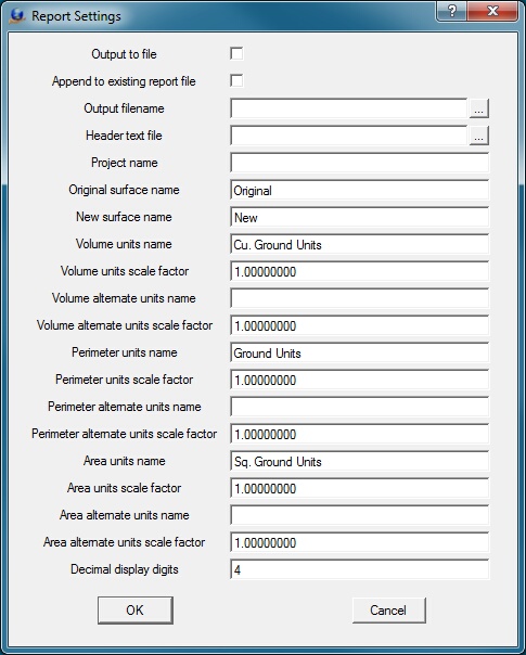
Output to file
If this is checked, volume information is written to a file.
Append to existing report file
If this is checked, and a report file is specified, volume information is appended to the report file if it already exists.
Output filename
Specifies the name of the output report file. Volume information is written in ASCII format to this file if the Output to file option is set.
Header text file
If a filename is specified, its contents will be added at the top of the report data. This must be a plaint text (ASCII) file.
Project name
Defines the project name to be displayed at the top of the report.
Original Surface name
Defines the name by which the original surface will be referred to in the report.
New Surface name
Defines the name by which the new surface will be referred to.
Volume units name
Specifies the postfix to append to the standard reported volumes.
Volume units
Defines the amount by which to multiply the standard volume. For example, if a job is in feet and the required reporting units are cubic yards, then a value of 0.0370 could be used to convert from cubic feet to cubic yards.
Volume alternate units name
Specifies the postfix to append to the alternate reported volumes. If this is left blank, no alternate volumes will be reported. This is useful if the volume needs to be reported in more than one unit format.
Volume alternate units scale factor
Defines the amount by which to multiply the alternate volumer. For example, if a job is in feet, and the required reporting units are cubic yards, then a value of 0.0370 could be used to convert from cubic feet to cubic yards.
Perimeter units name
Specifies the postfix to append to the standard reported perimeter.
Perimeter units scale factor
Defines the amount by which to multiply the standard perimeter.
Perimeter alternate units name
Specifies the postfix to append to the alternate reported perimeter. If this is left blank, no alternate perimeter will be reported. This is useful if the perimeter needs to be reported in more than one unit format.
Perimeter alternate units scale factor
Defines the amount by which to multiply the alternate perimeter
Area units name
Specifies the postfix to append to the standard reported area.
Area units scale factor
Defines the amount by which to multiply the standard area.
Area alternate units name
Specifies the postfix to append to the alternate reported area.. If this is left blank, no alternate area will be reported. This is useful if the area needs to be reported in more than one unit format.
Area alternate units scale factor
Defines the amount by which to multiply the alternate area.
Decimal display digits
Specifies the number of digits to display to the right of the decimal point for all reported values.
Compute
Press the button to begin the volume computation process. When processing is complete the results will display beneath this button.