Vr Mapping |
ON-LINE REFERENCE DOCUMENTATION CARDINAL SYSTEMS, LLC |
Set DTM Parameters (SetDtm)
Type: Parameter application
Sets parameters for DTM processing.
Detailed Description
Sets the parameters for the DTM (Digital Terrain Modeling) application. These parameters are used by the Run Dtm application. Parameters may be recorded and loaded.
NOTE: The key-in ParFilDTM may be used to load a DTM parameter file from a key-in which will make the saved parameters set here in effect during subsequent DTM processing with RunDtm. Example: ParFilDTM c:\jobs\BigJob\DtmRun.dtm
Available Key-ins
None
Parameters for Set DTM
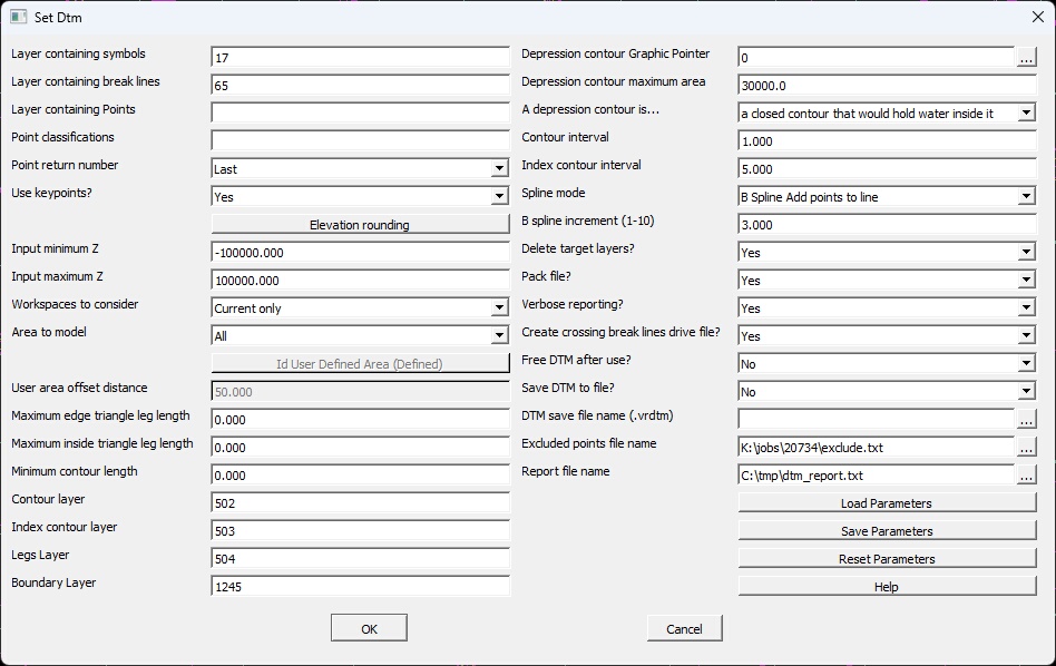
Set DTM dialog
Layer containing points
Specifies the layers to search for points (VrOne symbols) to use for DTM processing. A number line may be used.
Layer containing break lines
Specifies the layers to search for break lines to use for DTM processing. A number line may be used.
Layer containing Points
Specifies the layers to search for VrPoints (LiDAR) to use for DTM processing. This parameter may be used if the layer number has been set for this type of data. A number line may be used.
Point return number
If VrPoints (LiDAR) are being used as input for DTM processing, this parameter may be used to filter input points based on the LiDAR return number. Typically the LAST return is used when eliminating trees.
Use keypoints?
If VrPoints (LiDAR) are being used as input for DTM processing, this parameter may be used to specify that keypoints are to be used as input. Typically Bare Earth (BarEar) is performed on the VrPoint data, then the bare earth points are thinned using the Keypoint generation application. See Bare Earth and Keypoint for more information on these processes.
Elevation rounding
Rounds input elevations to 1, 2, or 3 decimal places. Options include the ability to round line elevation and VrPoint/Symbol elevations. Rounding can be to the nearest tenth, hundredth, or thousandth. The elevations in the VrOne file are not modified. Elevation rounding is available when using the FADE DTM engine. WARNING: Rounding input elevations will cause the DTM surface to be slightly different than the VrOne file.
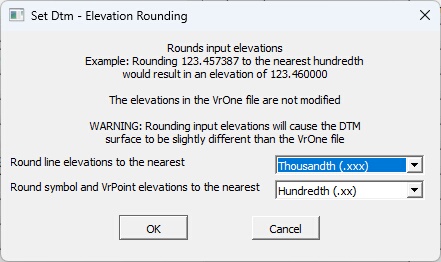
Elevation Rounding dialog
| • | Round like elevations to the nearest |
Round elevation option for lines. Options include Don't round, tenth (.x)", "hundredth (.xx)", or "thousandth (.xxx). For example, rounding 123.457387 to the nearest hundredth would result in an elevation of 123.460000.
| • | Round symbol and VrPoint elevations to the nearest |
Round elevation option for symbols and VrPoints. Options include Don't round, tenth (.x)", "hundredth (.xx)", or "thousandth (.xxx). For example, rounding 123.457387 to the nearest hundredth would result in an elevation of 123.460000.
Input minimum Z
Any points
Input minimum Z
Any points with Z values below this amount will be excluded from the DTM. This does apply when processing existing surface files.
Input maximum Z
Any points with Z values above this amount will be excluded from the DTM. This does apply when processing existing surface files.
Workspaces to consider
Defines the workspaces to consider when searching for DTM points and break lines. Options are Current only and All open workspaces.
Area to model
The entire data area or a smaller area may be modeled. Options are:
All |
All – The entire data area will be modeled. |
Current view window |
Current view window – Only the current view window will be modeled. This is useful when editing in an area to make regeneration of contours faster. |
User-defined area |
User-defined area – Models a user-defined polygon. The “Id User- Defined Area” button is used to select the user-defined area. |
Id User-Defined Area (Not defined or Defined)
Pressing this button will allow a line to be selected from any currently open VrOne workspace. Once a line has been selected, it will be used if “User-Defined Area” is selected for the Area to model option. The button label will change to indicate whether a user-defined area has been selected or not. NOTE: Just selecting a user-defined area does not mean it will be used, the Area to model option must also be set to “User-Defined Area”.
User area offset distance
If using a User-Defined Area, the size of the user-defined area will be increased by this amount. This allows points outside the user-defined area to be used when computing the TIN, which helps when matching one DTM area to another. The resulting contours are always trimmed to the exact user-defined area.
Maximum edge triangle leg length
Triangles will not be created if they contain a leg that is on the edge of the DTM that is longer than this length. This parameter may be set to 0 if all edge triangles should be created.
Maximum inside triangle leg length
Triangles will not be created if they contain a leg that is not on the inside of the DTM that is longer than this length. This parameter may be set to 0 if all inside triangles should be created.
Contour layer
Layer to into which to place intermediate contours. The range of this parameter is 1 to 10001. This parameter may be left blank if intermediate contours are not to be stored.
Index contour layer
Layer into which to place index contours. The range of this parameter is 1 to 10001. This parameter may be left blank if index contours are not to be stored.
Legs layer
Layer into which to place DTM surface triangles. This parameter may be left blank if triangles are not to be stored.
Boundary layer
Layer into which to place DTM boundary line. This line represents the smallest enclosing polygon that contains all of the DTM points. This parameter may be left blank if the DTM boundary is not to be stored.
Depression contour Graphic Pointer
Depression contours will be flagged using this graphic pointer. This parameter may be set to 0 if no depression contours should be flagged.
Depression contour maximum area
Depression contours with areas larger than this value will not be flagged.
Create depressions on closed contours only
If set to Yes, only contours that are physically closed will be considered for flagging.
Create depression on bottom contours only
If set to Yes, only contours at the bottom of a depression area will be considered for flagging.
Contour interval
Defines the intermediate contour interval. This parameter is entered in ground units. If zero is entered for this parameter, it will be set to one.
Index contour interval
Defines the index contour interval. This parameter is entered in ground units. If zero is entered for this parameter, it will be set to five times the contour interval.
Spline mode
Contour lines generated by Run Dtm may be splined using this parameter. Options include:
None Set to line mode 1 |
No splining will be done on contour lines. |
Spline Set to line mode 2 |
Set contour lines mode to Line mode 2, which is the VrOne cubic spline display mode. A cubic spline specifies that the line pass through all data points. This splining mode normally performs well for some planimetric features and manually digitized contours. However, it does not always produce cartographically correct contour lines. |
B Spline Add points to line |
Fits a B-spline through the contour line. The spline points will be placed on the line and stored in the VrOne file. This algorithm creates a cartographically correct line for contour lines from the DTM. |
Notes on the resulting lines from splining:
Spline Set to line mode 2 - This sets the contours to VrLine Mode 2, which displays a line with a cubic spline. This is a spline in which the line passes through all points. The resulting contour lines may be aesthetically pleasing but may not be as statistically correct as no splining.
B Spline Add points to line- This is a spline in which the line is approximated through the triangle edge contour points. The line may not pass through all points. The resulting contour lines may be aesthetically pleasing but may not be as statistically correct as no splining.
B spline increment (1-10)
Defines the smoothness of B-splined lines. For example, if a contour line began with 100 points as an un-splined line a B spline increment of 4 would result in a line of 400 points. A B spline increment of 4 is normally adequate for most contouring.
Delete target layers?
If this parameter is set to Yes then the Contour, Index contour and Legs layers will be deleted before a new DTM surface is generated.
Pack file?
If this parameter is set to Yes then the active VrOne workspace will be packed before a new DTM surface is generated.
Verbose reporting?
During DTM processing the progress will be reported in detail in a dialog box if this parameter is set to yes.
Free DTM after use?
If this parameter is set to No then the DTM surface generated will be retained in memory for later use. Retaining the surface in memory makes the DTM surface active for draping operations such as determining the DTM surface Z from the current Xy cursor location.
Save DTM to file?
If yes, then Run Dtm (RUNDTM) will save the DTM to the file specified in the “DTM Save file name” parameter. A DTM file contains the exact triangles that were created during DTM processing. After using RUNDTM once, Quick Dtm (QUIDTM) can then be used to create the DTM directly from the previously saved DTM file, resulting in much faster processing on large DTMs. This option is ideal if running the DTM engine multiple times on a large dataset that is not changing.
DTM Save file name
If “Save DTM to file?” is set to Yes, then the file will be saved to this file name. The file will have a default extension of vrdtm.
Excluded points file name
If a filename is specified, then any points that fall outside the minimum and maximum Z range will be written to this file. The format is a space delimited ASCII file with one point per line, in X Y Z order.
Report file name
If a filename is specified, then a list of the current DTM parameters and open Vr file names are written to this file. NOTE: This information is appended to the report file specified resulting in a large file over time.