Vr Mapping |
ON-LINE REFERENCE DOCUMENTATION CARDINAL SYSTEMS, LLC |
Plot (Plo)
Type: Utility application
Plots hardcopy or PDF files of VrOne vector and image files.
Detailed Description
Plots VrOne vector and (or) image files to one of six available formats. These formats include HPGL (Hewlett Packard Graphics Language), HPGL/2, HPGL/2 and HP RTL (Raster Transfer Language), PostScript, PDF, or System Printer.
The following chart shows feature availability for each plot format:
Format |
Vectors |
Image |
Color table |
Sheet Orientation |
Device DPI |
Minimum Line Width |
Render Mode |
HPGL |
Yes |
No |
No |
No |
No |
No |
No |
HPGL/2 |
Yes |
No |
Yes |
No |
No |
Yes |
No |
HPGL/2 and HP RTL |
Yes |
Yes |
Yes |
Yes |
Yes |
Yes |
Yes |
Postscript |
Yes |
Yes |
Yes |
No |
Yes |
No |
No |
Yes |
Yes+ |
Yes |
No* |
No |
Yes |
Yes |
|
System Printer |
Yes |
Yes+ |
Yes |
No* |
No* |
Yes |
Yes |
+ Plots multiple images
* May be set in the print preview dialog
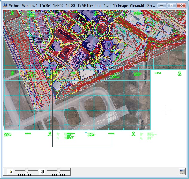
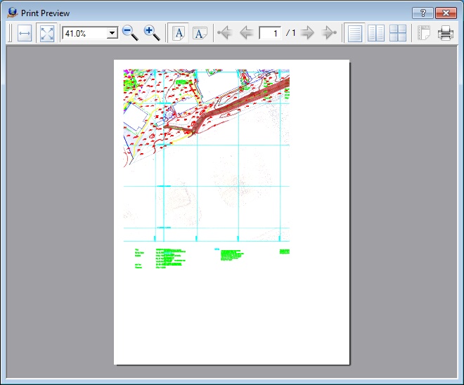
If the PDF or System Printer options are selected, a print preview dialog is displayed before printing begins. In the following images, the first image is the VrOne graphics window. The black rectangle encloses the area to be plotted. The second image displays the preview window with PDF selected as the Plot format. Note that the preview does not display images, but they will be sent to the print device.

VrOne graphics window with plot area defined

Plot preview window.
None

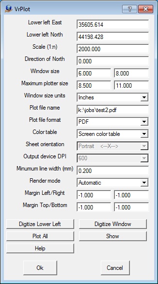
Lower left East, Lower left North
Defines the lower left East and North in ground units. Values for the lower left East and North may be typed in or may be defined by “Digitize Lower Left”, “Digitize Window” or “Plot All” is active.
Scale
Defines the plot scale. The plot scale is normally a job constant and is entered as a map scale ratio.
Direction of North
Defines the direction of North in reference to the plot window. Please see Direction of North for more information about this parameter.
Window size
Defines the plot window size in Inches or Millimeters. Values for the Window size may be typed or may be manually defined by “Digitize Window” if “Show” is active.
Maximum plotter size
Shows the maximum plotter sheet size. These parameters are displayed for information purposes and are not used by the plot application.
Window size units
Defines the units that the Window size and Maximum window size are displayed. Options are Inches and Millimeters.
Plot file name
Defines name of file in which to place plot information. This file may be later transferred to the plotter.
Plot file format
Defines output plot file format. Options are HPGL (Hewlett Packard Graphics Language), HPGL/2, HPGL2 and HP RTL (Raster Transfer Language), Postscript, PDF, and System Printer. When selecting System Printer, the default Windows system printer will be used, but may be changed by selecting the Printer icon in the print preview dialog.
Color table
Defines the color table to use during plotting. Options are:
| • | None – This setting is used when plotting HPGL files to older HP pen plotters such as the 7585 and DraftMaster series. With older pen plotters, the VrOne pen number will be used to pick up the corresponding plotter pen. It is possible to use this setting with newer raster plotters such as the HP DesignJet in which a VrOne pen number may be cross-referenced to a plotter pen number in the active pen palette. When using this mode with a newer raster plotter, the Palette setting must be set to Factory, Palette A, or Palette B. |
| • | Screen Color Table – The colors defined in the screen color table will be transferred to the plotter. VrOne pen numbers will be cross-referenced to the proper colors on the plotter. |
| • | Plotter Color Table – The colors defined in the plotter color table will be transferred to the plotter. VrOne pen numbers will be cross-referenced to the proper colors on the plotter. When plotting to a raster type plotter such as an HP DesignJet with HPGL/2 or HPGL/2 and RTL or PostScript this color table should be used. |
NOTE: By default the only difference between the screen color table and the plotter color table is the definition of pen number one. On the screen color table it is white and on the plotter color table, it is black. VrOne always uses the screen color table when displaying vectors in a graphics window and using the plotter color table will give the best color matching of vectors on the graphics screen and the plotter. Also note that color tables are not supported in all formats and are not supported on all plotters.
Sheet orientation
Defines the rotation of the plot. Portrait defines the X-axis as being along the front edge of the plotter while Landscape defines the Y axis as being along the front edge of the plotter.
Output device DPI
Defines the output DPI (Dots Per Inch). This should be matched to the target plotter. Selecting a DPI setting which is too low or too high may affect plot quality when plotting images. See suggested settings below.
Minimum line width
Defines the line width for the thinnest lines during plotting. This parameter is set in millimeters and a value of zero sets the thinnest line possible. For vectors only plots this parameter is normally set to the smallest value but when plotting vectors over image a wider line such as .35 may be selected.
Render mode
Sets the image render mode. Options are Automatic, Grayscale, Color, or Don’t specify. This parameter is available only for the HPGL/2 and RTL plot format. Normally the render mode is set to automatic in which Grayscale or Color is chosen depending on the pixel depth. Some plotters such as the HP DesignJet 1055 do not plot color vectors when plotting a grayscale image when the render mode is set to Automatic or Grayscale. In this case a render mode of “Don’t specify” should be used.
Margin Left/Right
For PDF and System Printer modes, sets the left and right margins in inches or millimeters to use between the sheet edge and the selected plot window. A -1 indicates that the printer default should be used.
Margin Top/Bottom
For PDF and System Printer modes, sets the top and bottom margins in inches or millimeters to use between the sheet edge and the selected plot window. A -1 indicates that the printer default should be used.
Digitize Lower Left
Allows the digitizing of the lower left corner of the plot in the VrOne graphics window. The current window size and direction of north are used from the dialog box.
Digitize Window
Allows digitizing of the lower left corner and upper right corner of the plot in the VrOne graphics window. The lower left East, lower left North and window size are modified by this operation.
Plot All
Fits a plot window around all open VrOne and image data. The lower left East, lower left North and window size are modified by this operation
Show
Reads the current window data from the dialog box and displays a plot window in the VrOne graphics window. If values such as lower left East or North, scale, or window size are changed in the plot dialog box this button should be pressed to update the graphics window.
NOTE: Plotters from the same manufacturer may behave differently using the same settings. It is suggested that test plots be performed to determine the best settings for the plotter being used.
NOTE: This plot application can plot images larger than the physical memory in the plotter when using HPGL/2 and RTL format. First defining the vectors and then rotating image memory so that the image scan lines are parallel with the X plotter head movement accomplishes this. Once a scan line has been received the plotter will process and plot it while still receiving plot data. Unfortunately, this feature limits the number of images that can be plotted to one.
NOTE: By default the only difference between the screen color table and the plotter color table is the definition of pen number one. On the screen color table it is white and on the plotter color table, it is black. VrOne always uses the screen color table when displaying vectors in a graphics window and using the plotter color table will give the best color matching of vectors on the graphics screen and the plotter. Also note that color tables are not supported in all formats and are not supported on all plotters.
Plotter |
Color Table |
Output DPI |
Render Mode Grayscale Image |
Render Mode Color Image |
HP-7580/85 |
None |
NA |
NA |
NA |
HP-DraftMaster |
None |
NA |
NA |
NA |
HP-650C |
Plotter |
300 |
Automatic |
Automatic |
HP-750C |
Plotter |
300 |
Automatic |
Automatic |
HP-755CM |
Plotter |
300 |
Don’t specify |
Don’t specify |
HP-1033 |
Plotter |
300 |
Automatic |
Automatic |
HP-1050C |
Plotter |
600 |
Don’t specify |
Don’t specify |
HP-1055 |
Plotter |
600 |
Don’t specify |
Automatic |
HP-3500CP |
Plotter |
600 |
Don’t specify |
Don’t specify |
Transferring Plot Files to Plotter via FTP
The VrOne plot application creates a plot file on disk. This plot file must then be transferred to the plotter for hard copy output. Many of the newer plotters such as the HP 1055C can be connected to the network and run an FTP (File Transfer Program) server. This allows files to be transferred via FTP. Please find following an example of transferring a plot file to a HP 1055C. This operation is done from a Windows Command Prompt window. Items in bold italic are typed by the user and may be different on various systems. Return may be pressed when for User: and Password:, they are not required.
C:\> cd \jobs\job123
C:\jobs\job123>ftp 192.168.1.99
Connected to 192.168.1.99.
220 JD FTP Server Ready
User (192.168.1.99:(none)):
331 Username OK, send identity (email address) as password.
Password:
230- Hewlett-Packard J3113A FTP Server Version 1.0
Directory: Description:
---------------------------
PORT1 Print to port 1 DesignJet 1055CM (C6075A)
To print a file, use the command: put <filename> [portx]
or 'cd' to a desired port and use: put <filename>.
Ready to print to PORT1
230 User logged in.
ftp> put sheet1.plt
200 PORT command successful.
150 Opening data connection.
226- Ready
226- Processing job
226 Transfer complete.
ftp: 2688079 bytes sent in 20.09Seconds 133.78Kbytes/sec.
ftp> bye
221 Goodbye
Transferring Plot Files Via the Print Spooler
The VrOne plot application creates a plot file on disk. This plot file must then be transferred to the plotter for hard copy output. Plotters may be connected to a network or may be connected to a computer with a printer cable. Files may be sent to the plotter using the print spooler. The print spooler must be set up before this can be done. Following are some notes on installing the necessary software to use print spooling on Windows NT 4.0. Note that IP addresses such as 192.6.1.82 will probably be different on various systems. This process is similar on Windows 2000 and is not possible on Windows 95/98/ME. The following information is provided as a guide. Please consult with your system administrator before using the following information.
Setting up LPR on Windows NT 4.0
My Computer -> Printers -> Add Printer
Select "My Computer" [Next>]
[Add Port] Highlight "LPR Port" [New Port]
(If LPR Port is not lised, install Microsoft TCP/IP Printing. See below)
Name or address of server providing lpd: 192.6.1.82
Name of printer or print queue on that server: djet_2
[OK] [Close]
Make sure that port just created has check next to it. [Next]
Select plotter:
Manufacturers: HP
Printers: Hewlett-Packard HP-GL/2 Plotter
usage: lpr -S192.6.1.82 -Pplot FILENAME
lpr -Sdjet_2 -Pplot FILENAME
Installing Microsoft TCP/IP Printing on Windows NT 4.0
Right click Network Neighborhood -> Properties
Select Services Tab
Push Add button
Double click Microsoft TCP/IP Printing
(When loading from CD the directory should be: E:\I386)
| • | Long axis plots (over 51 inches) is possible with the HPGL2 driver only. |
| • | If the X-axis is greater than the Y-axis then the plotter rotation on the front panel should be set to zero. |
| • | If the Y-axis is greater then the X-axis then the plotter rotation of the front panel should be set to 270. |