Vr Mapping |
ON-LINE REFERENCE DOCUMENTATION CARDINAL SYSTEMS, LLC |
Point Display (PoiDis or PO)
LiDAR
Type: Display Management
Allows user to manage the parameters that control the display of Points.
Adjust Clip Limits on Recenter
Several point display criteria may be controlled. Points may be filtered based on Z Slice, classification, return number, sensor number, flight/strip number, GPS time, scan angle and/or keypoint. Any or all of these filters may be selected. When displaying Points in 3D VrThree and 2.5D VrThree, near and far clip limits may be applied to help isolate points within a viewing slice based on the 3D eye point position and direction.
Points may be colored based on layer (entity), LiDAR intensity, classification, RGB color values, point elevations or Z slice, sensor number, or flight/strip number. Many of the color display modes include additional parameter settings. Any of the coloring options such as elevation may be supplemented by draping the Intensity values which offers a dual coloring method in most configurations.
Several reporting applications are available including a LiDAR intensity histogram and the LiDAR classification use.
Other key-in commands that further control Point display include the Point Density (PD) command which allows the skipping of points during display and Point Size (PS) command which controls the size of the Points during display . The parameters defined in Point Display (PoiDis) are used when displaying Points in the VrOne 2D window, VrTwo stereo with images or LiDARgrammetry images and in 3D VrThree.
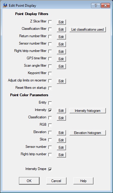
Point Display main dialog box
The Point Display dialog box is divided into the Point Display Filters area and the Point Color Parameters.
| • | The Point Display Filters display points based on one or more criteria. |
| • | The Point Color Parameters define the coloring scheme when points are displayed. One of the six color options may be active at a time. |
Multiple point display filters may be checked. For example, it would be possible to display only points that are classified as vegetation a last return number in the elevation range of 100 to 120 ground units.
Pressing the Edit button to the right of the checkbox will allow the definition of parameters for that point display filter.
Point Display Filters - Z Slice
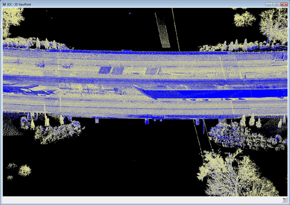
Displays a slice of Point data that is defined as an elevation range. This filter is useful when some of the point data obscures other data such as decks, tunnels and areas of tree cover. The Z Slice filter may be turned on/off with the check box. The following is an example of a Z Slice applied to an overpass area in which LiDAR data was collected both on a highway overpass and on the roadway under the overpass. By using the Z Slice filter, either the overpass or the roadway may be isolated for viewing and data collection.
Points with an elevation in the Z Slice range will be displayed if the point passes other active point filters also.
The interactive application Point Set Z (PoiSetZ) is also available which allows the definition of the Z Slice parameters with the option to digitize the base elevation.
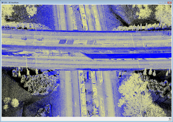
Overpass area with all data displayed
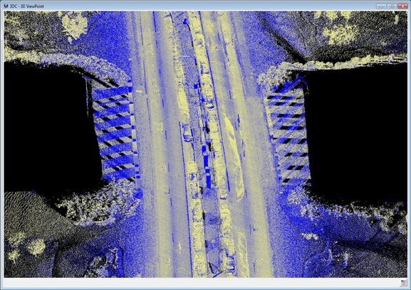
Overpass area with Z Slice showing roadway without bridge deck
Overpass area with Z Slice showing bridge deck without road
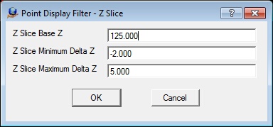
The Z Slice parameter dialog
Z Slice Base Z
Defines the elevation base for the Z Slice in ground units.
Z Slice Minimum Delta Z
Defines the lower range of the Z slice using a delta Z from the base Z. This value is typically a negative number. The example in the above dialog would set the Z Slice range from 123 to 130.
Z Slice Maximum Delta Z
Defines the upper range of the Z slice using a delta Z from the base Z. This value is typically a positive number. The example in the above dialog would set the Z Slice range from 123 to 130.
Point Display Filter - Classification
Defines up to 32 LiDAR Classifications to be displayed. Points with these classifications will be displayed if the point passes other active point filters also. The "Check all" button selects all classifications and the "Uncheck all" de-selects all classifications.
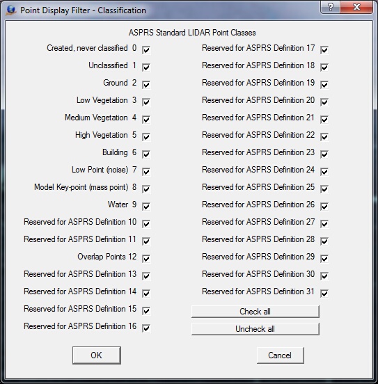
The Point Display Filter for Classifications
List Classifications Used - Point Color Parameters
Pressing the "List classifications used" button will display the LiDAR Classifications that are used in the currently opened VrOne files.
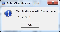
Results of "List classifications used"
Point Display Filter - Return Number
The LiDAR Return Number is the pulse return number for a given output pulse. A given output laser pulse can have many returns. They are marked in sequence of return. A single output pulse may have up to five returns. The Return Number filter defines and displays only the points that match the specified return number.
Points with the user specified return number will be displayed if the point passes other active point filters also.
Pressing the Edit button will display the following dialog and allow the definition of the return number to display.
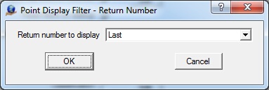
The Return Number dialog
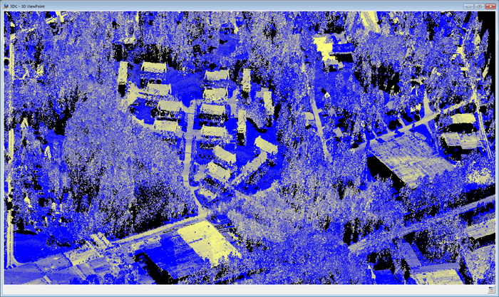
The Return Number may be from one to five or the last return. Typically the Points with the last return are the lowest points and considered to be on the ground. By selecting the last return, many points in vegetation and trees are not displayed. In the examples below, one scene from 3D VrThree displays LiDAR Point data will all the returns. Another shows only the last returns.
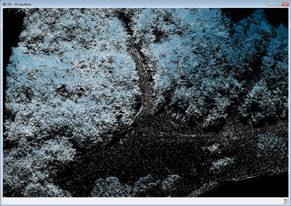
A scene from 3D VrThree showing LiDAR Point data will all returns
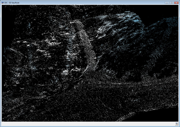
A scene from 3D VrThree showing LiDAR Point data will the last return only
Point Display Filter - Sensor Number
LiDAR collection platforms such as mobile LiDAR may use more than one sensor that work simultaneously. The Sensor Number parameter allows filtering by up to eight sensor numbers. On input, the sensor number may be embedded in the input file name. Starting at LAS version 1.4, the sensor number is a point attribute in this format. A number line may be entered for this parameter.
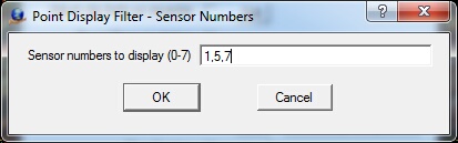
Sensor number filter dialog
Point Display Filter - Flight/strip number
Each point in the VrPoint (LiDAR) database has an attribute for the storage of the flight or strip number. In aerial applications, this number may indicate a flight line number; in mobile LiDAR collection, it may indicate a pass number. On input the flight/strip numbers may be embedded in the input file name. This attribute is not part of the LAS format. A number line may be entered for this parameter.

Flight/strip number filter dialog.
Point Display Filter - GPS Time
If the VrPoints are saved with the available GPS time, points may be filtered based on a minimum and maximum GPS time. The parameters are typically expressed in seconds from a known start time.
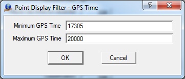
GPS Time filter dialog
Point Display Filter - Scan Angle
VrPoints may be filtered by their scan angle attribute. This may be useful when isolating the points directly under the sensor. The Scan Angle is entered in degrees.
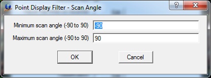
Scan Angle filter dialog
Point Display Filter - Keypoint
Keypoints or model Keypoints are used to thin LiDAR datasets by identifying points in flat areas that represent other LiDAR points nearby to be within the same user defined elevation tolerance. When the keypoint filter is active only VrPoints that are defined as keypoints are displayed.
Point Display Filter - Adjust Clip Limits on Recenter
This parameter is used only by the VrThree (VrLiDAR) 3D VrThree environment. If checked, it adjusts the near and far clip limits each time the screen is re-centered. The Edit button allows the definition of the near and far clip and clip increment values. See Getting Started with 3D VrThree for information for turning on/off and changing the near and far clip limits interactively while in 3D VrThree.
When viewing Point data in 3D VrThree, clipping planes are used to prevent the display of data that is "near to" or "far away" from the viewer's eye point or center of projection. The planes are perpendicular to the camera and set at user definable distances from the 3D center of the current scene. The near clip place is set in front of the 3D center and the far clip plane is set behind it. The clipping planes are useful when using ground based LiDAR in situations such as tunnels, roadway overpasses or other data in which data outside the current area of interest obscures or overlays this area. The clip limits are also useful when using aerial LiDAR to help minimize tree cover.
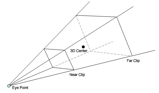
Near and far clip diagram
The following two ground based static LiDAR examples show a 3D scene in which a tree obscures the area of interest then the result of the application of a near clip to remove the tree from the view. Once the near clip is activated and positioned, the user can move the eye point closer to the area for viewing and data collection and measurements. The eye point may also be rotated in any direction in X Y and Z and the near and far clips will remain in effect allowing the area of interest to be viewed from any angle and at any scale.
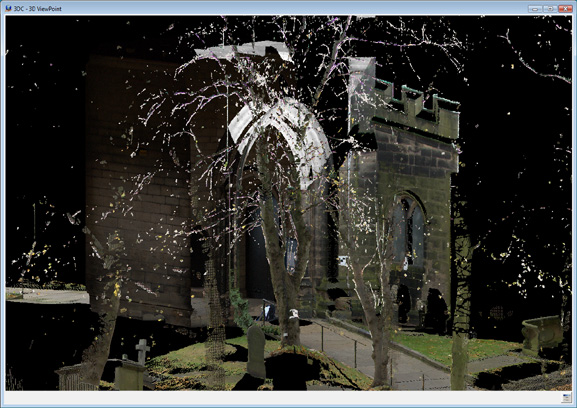
A scene from 3D VrThree showing a tree obscuring the area of interest
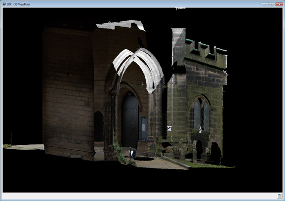
A scene from 3D VrThree showing the result of the application of a near clip
The values entered into the Near/Far Clip dialog are in arbitrary units from 1-100. The near and far clip distances may be edited interactively when clips are on in the 3D VrThree environment. If the "Adjust clip limits on recenter" is checked then the near and far clip distances will be modified when a new 3D center for the view is computed (recentered).

The Near/Far Clip dialog
Near Clip Distance (1-100)
Defines the distance from the 3D center of the view to the near clip plane.
Far Clip Distance (1-100)
Defines the distance from the 3D center of the view to the far clip plane.
Clip Display Increment (1-100)
Defines the near and far clip distance increment to add or subtract from the existing near and far clip distances when editing these values interactively.
Point Display Filter - Reset Filters on Startup
If this parameter is checked, the Z Slice filter, classification filter, return number filter will be unchecked and the Adjust clip limits on re-center will be checked when VrOne or VrTwo is started.
The Point Color Parameters define the coloring scheme when points are displayed. Not all color options are supported by all LiDAR (Point) data sets. For example, RGB is typically not used for aerial based LiDAR.
Only one point color checkbox may be active. Pressing the Edit button to the right of the checkbox will allow the definition of parameters for that point color item.
Point Color Parameters - Entity
The Entity color option colors VrPoints (LiDAR) by their layer numbers. This method uses the same method lines, symbols and text use to set colors which is with pen numbers. VrPoints are colored using the same color parameters that are used to color Vr Symbols using a pen table.
Point Color Parameters - Intensity
Each point in the database carries an intensity along with many other LiDAR point attributes. Intensity is one of the most popular methods used for coloring points.
In the measurement of light, intensity means irradiance, which is optical power per unit area (watts per square meter). The imprecise definition would be how much light (watts) the instrument received. There are a number of factors that affect the intensity value:
| 1. | How much light was sent out; |
| 2. | Range to the target; |
| 3. | Attenuation of beam by atmosphere; |
| 4. | Reflectance of target (at the appropriate wavelength); |
| 5. | Incident angle of light on the target surface; |
| 6. | Size of receiver aperture; |
| 7. | Efficiency of receiver optics at focusing the return light onto receiver sensor; |
| 8. | Specularity reflection of the target surface. |
Point Color Parameters - Intensity Histogram
The range of intensity vary between different LiDAR sensors and manufacturers. The Intensity histogram button displays a dialog containing the intensity range and point counts of the intensity values in the currently opened VrOne files.

The Intensity histogram dialog
The above intensity histogram shows an intensity range from 0 to 255 however the majority of the point intensities are in the range of 0 to approximately 50. Moving the cursor over the histogram area of the dialog displays the intensity value and the number of points that have that value.
Point Color Parameters - Intensity Edit
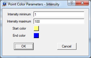
The Intensity parameter dialog
The Intensity histogram may be used to determine the usable intensity value range of the currently opened VrOne files (see Intensity Histogram).
Intensity Minimum
Defines the minimum intensity value for which the start color will be assigned.
Intensity Maximum
Defines the maximum intensity value for which the end color will be assigned.
Start Color
Defines the start color value. Press the color square to change the color assignment. Point colors will be blended from the start color to the end color for point intensities between the minimum and maximum intensities.
End Color
Defines the end color value. Press the color square to change the color assignment. Point colors will be blended from the start color to the end color for point intensities between the minimum and maximum intensities.
Point Color Parameters - Classification
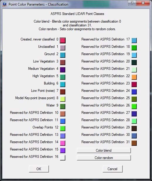
User-defined colors may be assigned to each of the 32 ASPRS standard LiDAR point classes.
Point Color Parameters - Classification Edit
Color values may be assigned by pressing the color squares. The "Color blend" button will blend color assignments between classification 0 and classification 31. Classification 0 is the start color and classification 31 is the end color. The "Color random" button sets color assignments randomly for the 32 classifications.
The Intensity color assignment dialog
The point data base contains three color channels for each LiDAR point if these values exist. These fields are used to color each point and are normally obtained using secondary data, typically a camera. Checking this options will use these values. White will be used if RGB is not available.
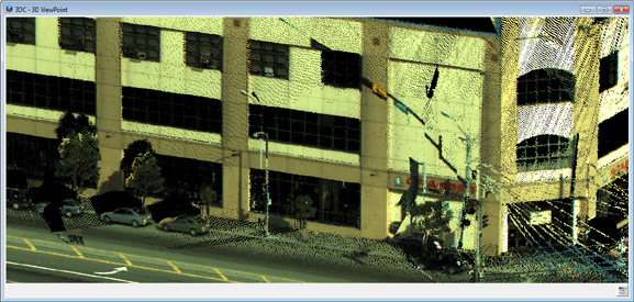
LiDAR points with RGB assignments
Point Color Parameters - Elevation
Colors points by elevation. Not all LiDAR data contains point intensities, classifications, or RGB values, but the data always contains elevations for each point. The option to color points using elevations is always available.
Point colors based on elevation
Points that fall below the minimum defined elevation will use the start color and points that fall above the maximum defined elevation will use the end color.
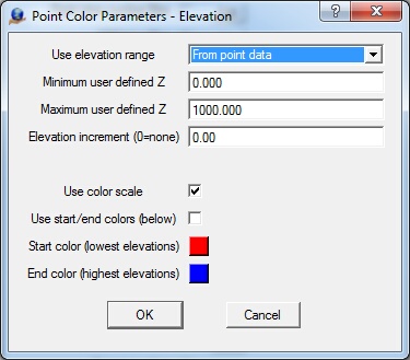
Point Color Parameters - Elevation dialog
Use elevation range
When displaying point colors based on elevation, the elevation range may be defined "From Point data" or "From a user defined Z range". If "From user defined Z range" is selected then the minimum and maximum user defined Z will be used.
Minimum user defined Z
If the "Use elevation range" option is set to "From user defined Z range", this value will be used for the minimum elevation when setting point colors.
Maximum user defined Z
If the "Use elevation range" option is set to "From user defined Z range", this value will be used for the maximum elevation when setting point colors.
Elevation increment (0=none)
If this parameter is set to a non zero positive number, the Point colors will be held to a constant value for this elevation increment (see example below). When this parameter is set to zero, the point colors are evenly blended from the minimum defined elevation to the maximum defined elevation.
Use color scale
Using the color scale defines the color for the lowest elevations to the highest in a predefined, broad color range. This setting overrides the "Start color" and "End color" parameters.
Use start/end colors (below)
When checked, the "Start color" and "End color" parameters will be used to define the colors for the lowest to highest elevations.
Start color (Lowest Elevations)
Defines the start color value for the lower elevation. Press the color square to change the color assignment. Point colors will be blended from the start color to the end color for elevations between the minimum and maximum elevation range.
End color (Highest Elevations)
Defines the end color value for the highest elevation. Press the color square to change the color assignment. Point colors will be blended from the start color to the end color for elevations between the minimum and maximum elevation range.

Point colors based on elevation using the Elevation Increment option
Point colors based on elevation using start and end colors of red and blue
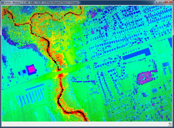
Point colors based on elevation using color scale
Point Color Parameters - Elevation Histogram
The Elevation histogram button displays the elevation range values of the VrPoints in the currently opened VrOne files.
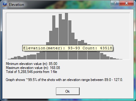
Elevation histogram
Point Color Parameters - Slice
This option allows the setting of individual colors for user defined elevation ranges. This option is useful when elevation ranges need to be identified.
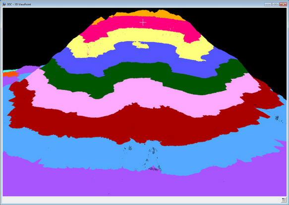
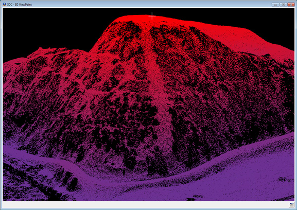
Scene from 3D VrThree of Mount St. Helens showing color slices
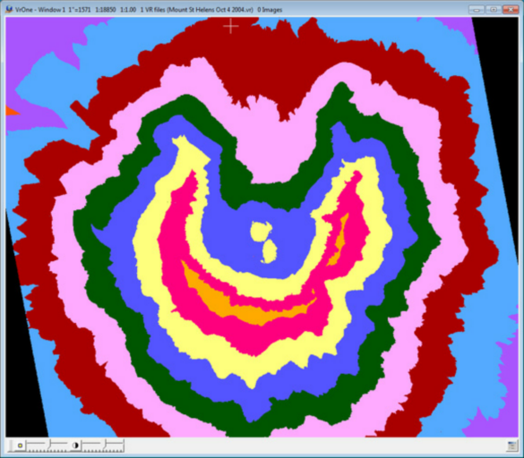
Scene from VrOne of Mount St. Helens showing color slices
Up to 20 elevation slices may be defined. If both the minimum and maximum elevations are set to zero the slice will not be used.
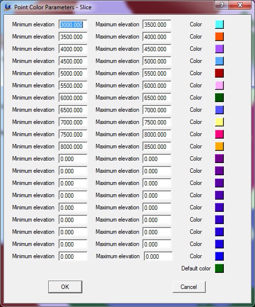
Point Color Parameters -Slice Dialog
Minimum User Defined Z
Defines the minimum elevation for the Z slice in ground units.
Maximum User Defined Z
Defines the maximum elevation for the Z slice in ground units.
Color
Shows the current color for the Z slice. Press the color square to change the color.
Point Color Parameters - Sensor Number
LiDAR collection platforms such as mobile LiDAR may use more than one sensor that work simultaneously. The Sensor Number parameter allows filtering by up to eight sensor numbers. On input, the sensor number may be embedded in the input file name. Starting at LAS version 1.4, the sensor number is a point attribute in this format. Selecting "Sensor number" colors points based on up to eight sensor numbers.
Color values may be assigned by pressing the color squares. The "Color blend" button will blend color assignments between sensor number 0 and sensor number 7. Sensor color 0 is the start color and sensor color 7 is the end color. The "Color random" button sets color assignments randomly for the 8 sensors.
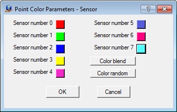
Point Color Parameters - Sensor color dialog
Point Color Parameters - Flight/strip Number
Each point in the VrPoint (LiDAR) database has an attribute for the storage of the flight or strip number. In aerial applications, this number may indicate a flight line number; in the case of mobile LiDAR collection, it may indicate a pass number. On input, the flight/strip numbers may be embedded in the input file name. This attribute is not part of the LAS format. Selecting "Flight/strip number" will color points based on their flight/strip number.
Color values may be assigned by pressing the color squares. The "Color blend" button will blend color assignments between flight/strip number 0 and flight/strip number 255. Sensor color 0 is the start color and sensor color 255 is the end color. The "Color random" button sets color assignments randomly for the 256 flight/strip numbers.
There are 256 possible flight numbers from 0 to 255. 64 of these flight/strip numbers are displayed in the dialog at one time. Pressing the Previous or Next buttons will move between the four possible pages.

Point Color Parameters - Flight/Strip Number dialog
Point Color Parameters - Intensity Drape
When coloring VrPoint (LiDAR) data using any of the coloring options (except Intensity) it is possible to add intensity coloring in addition to the current coloring option. Selecting "Intensity Drape" will turn this coloring addition on.
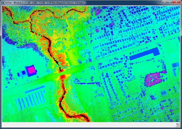
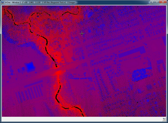
Point colors based on elevation using color scale without Intensity Drape
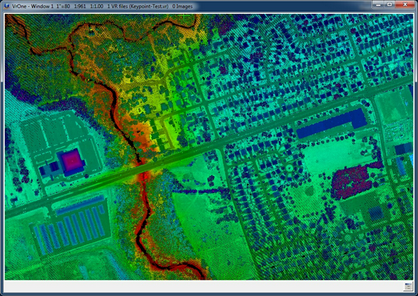
Point colors based on elevation using color scale with Intensity Drape
Following are equivalent Vr key-ins for conditioning the Point Display parameters.
Description |
Key-in |
Keyword |
Parameters |
Example |
|
|
|
|
|
Point Display Filter - Z Slice - On/Off |
PoiFilZsl |
On|Off|Tog |
|
PoiFilZsl On |
Point Display Filter - Z Slice - Set Base Z |
PoiFilZsl |
BasZ |
BaseZ |
PoiFilZsl BasZ 117.0 |
Point Display Filter - Z Slice - Set Z Range |
PoiFilZsl |
RanZ |
RangeZ |
PoiFilZsl RanZ 4.0 |
Point Display Filter - Minimum Delta Z |
PoiFilZsl |
MinDel |
Minimum Delta Z |
PoiFilZsl MinDel -2.0 |
Point Display Filter - Minimum Delta Z |
PoiFilZsl |
MaxDel |
Maximum Delta Z |
PoiFilZsl MaxDel 5.0 |
|
|
|
|
|
Point Display Filter - Classification - On/Off |
PoiFilCla |
On|Off|Tog |
|
PoiFilCla On |
Point Display Filter - Classification - Set |
PoiFilCla |
Set |
NumberLine (0-31) On|Off |
PoiFilCla Set 0-5;7;14 On |
|
|
|
|
|
Point Display Filter - Return Number - On/Off |
PoiFilRet |
On|Off|Tog |
|
PoiFilRet On |
Point Display Filter - Return Number - Return number to display (0=Last) |
PoiFilRet |
RetNum |
0-5 |
PoiFilRet RetNum 0 |
|
|
|
|
|
Point Display Filter - Sensor Number - On/Off |
PoiFilSen |
On|Off|Tog |
|
PoiFilSen On |
Point Display Filter - Sensor Number - Sensor numbers to display |
PoiFilSen |
Set |
NumberLine (0-7) On|Off |
PoiFilSen Set 0;3-5 On |
|
|
|
|
|
Point Display Filter - Flight/Strip Number - On/Off |
PoiFilFli |
On|Off|Tog |
|
PoiFilFli On |
Point Display Filter - Flight/Strip Number - Strip numbers to display |
PoiFilFli |
Set |
NumberLine (0-255) On|Off |
PoiFilFli Set 0-5;7;14 On |
|
|
|
|
|
Point Display Filter - GPS Time - On/Off |
PoiFilGps |
On|Off|Tog |
|
PoiFilGps On |
Point Display Filter - GPS Time - Min time to display |
PoiFilGps |
Min |
GPS Time |
PoiFilGps Min 1000 |
Point Display Filter - GPS Time - Min time to display |
PoiFilGps |
Max |
GPS Time |
PoiFilGps Max 5000 |
|
|
|
|
|
Point Display Filter - Scan Angle - On/Off |
PoiFilSca |
On|Off|Tog |
|
PoiFilSca On |
Point Display Filter - Scan Angle - Min Scan Angle to display |
PoiFilSca |
Min |
Angle (degrees) |
PoiFilSca Min -20 |
Point Display Filter - Scan Angle - Max Scan Angle to display |
PoiFilSca |
Max |
Angle (degrees) |
PoiFilSca Max 20 |
|
|
|
|
|
Point Display Filter - KeyPoint - On/Off |
PoiFilKey |
On|Off|Tog |
|
PoiFilKey Tog |
|
|
|
|
|
Point Display FIlter - Turn all filters off |
PoiFilOff |
|
|
PoiFilOff |
|
|
|
|
|
Point Color Parameters - Entity (Color by layer) - On |
PoiColEnt |
On |
|
PoiColEnt Off |
|
|
|
|
|
Point Color Parameters - Intensity - On |
PoiColInt |
On |
|
PoiColInt On |
Point Color Parameters - Intensity - Intensity minimum |
PoiColInt |
Min |
Intensity |
PoiColInt Min 100 |
Point Color Parameters - Intensity - Intensity maximum |
PoiColInt |
Max |
Intensity |
PoiColInt Max 4096 |
Point Color Parameters - Intensity - Start color |
PoiColInt |
StaCol |
R-G-B |
PoiColInt StaCol 20-40-255 |
Point Color Parameters - Intensity - End color |
PoiColInt |
EndCol |
R-G-B |
PoiColInt EndCol 125-50-255 |
|
|
|
|
|
Point Color Parameters - Classification - On |
PoiColCla |
On |
|
PoiColCla On |
Point Color Parameters - Classification - Set color |
PoiColCla |
Col |
Classification# R-G-B |
PoiColCla Col 5 75-0-255 |
|
|
|
|
|
Point Color Parameters - RGB - On |
PoiColRgb |
On |
|
PoiColRgb On |
|
|
|
|
|
Point Color Parameters - Elevation - On |
PoiColEle |
On |
|
PoiColEle On |
Point Color Parameters - Elevation - Elevation range source |
PoiColEle |
Sou |
Poi | Usr |
PoiColEle Sou Poi |
Point Color Parameters - Elevation - Minimum user defined Z |
PoiColEle |
MinZ |
Elevation |
PoiColEle MinZ 630.0 |
Point Color Parameters - Elevation - Maximum user defined Z |
PoiColEle |
MaxZ |
Elevation |
PoiColEle MaxZ 860.0 |
Point Color Parameters - Elevation - Elevation increment (0=none) |
PoiColEle |
EleInc |
ElevationIncrement |
PoiColEle EleInc 5.0 |
Point Color Parameters - Elevation - Start color for lowest elevation |
PoiColEle |
StaCol |
R-G-B |
PoiColEle StaCol 25-45-75 |
Point Color Parameters - Elevation - End color for highest elevation |
PoiColEle |
EndCol |
R-G-B |
PoiColEle EndCol 125-50-255 |
Point Color Parameters - Elevation - Color scale type to use |
PoiColEle |
ScaTyp |
Sca|Usr|Tog (Scale or User) |
PoiColEle ScaTyp Sca |
|
|
|
|
|
Point Color Parameters - Slice - On |
PoiColSli |
On |
|
PoiColSli On |
Point Color Parameters - Slice - Slice elevations |
PoiColSli |
SliZ |
Index MinZ MaxZ |
PoiColSli SliZ 10 3000.0 3500.0 |
Point Color Parameters - Slice - Color for elevation slice |
PoiColSli |
SliCol |
Index R-G-B |
PoiColSli SliCol 10 120-80-10 |
Point Color Parameters - Slice - Default color |
PoiColSli |
DefCol |
R-G-B |
PoiColSli DefCol 255-0-255 |
Point Color Parameters - Slice - Reset elevation parameters |
PoiColSli |
ResZ |
|
PoiColSli ResZ |
|
|
|
|
|
Point Color Parameters - Sensor - On |
PoiColSen |
On |
|
PoiColRgb On |
|
|
|
|
|
Point Color Parameters - Flight/strip Number On |
PoiColFli |
On |
|
PoiColFli On |
|
|
|
|
|
Point Color Parameters - Intensity Drape - On/Off |
PoiColIDr |
On|Off|Tog |
|
PoiColIDr On |
Point Display Key-In Parameter Notes
| • | Number Line - Blanks and commas are used to separate commands on a Vr key-in. When using a number line, semicolons, colons, or stars should be used to separate the fields. For example: to specify classifications 0, 1, 2, 3, 4, 5, 7, 14, the number line "0-5;7;14" could be used. |
| • | Tog - When Tog is listed as a keyword or parameter option, it may be used to toggle the current value. For example, if the classification filter were turned on, "PoiFilCla Tog" would turn it off. |
| • | Red Green Blue (RGB) values - The red, green and blue values that define a color are separated with a dash. For example, 127-255-212 would define the color aquamarine. |
| • | Point Filters - Multiple point filters (PoiFil) can be active. |
| • | Point Color - Only one point color (PoCol) mode can be active. When a mode is selected the previous color mode is de-selected. |
| • | Point Color Parameters - Slice - The Index is the elevation slice number. There may be up to 20 elevation slices. The range of Index is from 1 to 20. |