Vr Mapping |
ON-LINE REFERENCE DOCUMENTATION CARDINAL SYSTEMS, LLC |
Vr Mosaic
Type: Stand-alone Application (vrmosaic.exe)
Mosaicing Application.
See also: Tutorial Vr Mosaic
This application will create mosaic images from multiple ortho images. Ortho images may come from any source (such as VrOrtho) that outputs TIFF (.tif) images with TIFF world (.tfw) files.
VrMosaic is built on the Vr Mapping engine, and shares many attributes in common with VrOne. VrMosaic contains a subset of the standard commands available in VrOne. Detailed documentation on each command can be found in the main VrOne documentation files. VrMosaic uses standard VrOne compatible files to store seam lines. VrMosaic provides advanced tools for placing and editing the seams. The VrMosaic seam line editor provides a real-time preview option that dynamically shows how the ortho images will be merged as the seam lines are edited. This provides instant feedback during seam line editing, and allows for precise matching of features between orthos as well as easy blunder detection. Once seam lines have been defined and edited, the final mosaic images may be created by selecting an output area, or using a batch mode that uses an existing sheet layout.
The batch mode option will create multiple output mosaic images by using standard VrOne lines to define the sheet borders. The lines may be placed using the Insert Line command in VrMosaic, or by using VrOne. Mosaic images may be written as 24-bit color or 8-bit grayscale, regardless of the type of the original ortho image type. Down sampled mosaic images may be created by selecting different pyramid levels. Output of JPEG compressed mosaic images is also supported with user control of the compression quality setting.
This is an example work flow using Vr Mapping software to create mosaics from raw photos to finished product.
1. Obtain raw photos in digital form.
2. Create new project using VrOrtho and define project settings and add raw photos to project.
3. Orient photos using VrOrtho single photo resection or by importing orientation data.
4. Define ortho areas using VrOrtho (using default settings or by using ortho area editor), or by using OrthoLayout application in VrOne.
5. Create ortho images using VrOrtho.
6. Create a new Project in VrMosaic, and add the ortho images to the project.
7. Use the VrMosaic application to define seam lines and create final output mosaic images.
VrMosaic will start by opening the Main Window and one Graphics window.
Starting an Application (Command)
Pulling down a menu and selecting an item may start commands. Commands may also be started from a key-in using the command name. Each command name is the first three letters of the first two words on the pull down. For example: The command name for Edit Line is EdiLin If this rule is not followed the correct key-in is listed in parenthesis in the pull down menu after the command.
The Main Window
The Main Window in VrMosaic contains the command pull down menus, a key-in area, two information areas, a progress bar and the coordinate display.
Commands names may be typed into the key-in area at almost any time.
On the border of the Main Window is shown the active workspace. Workspaces are VrOne compatible files that are used to store seam lines and sheet layouts.
Overview
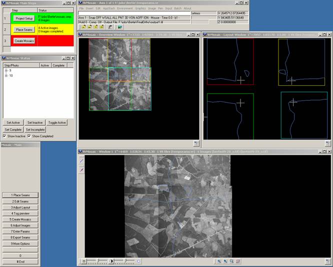
VrMosaic provides several applications to help in the mosaic process. The main application used in creating Mosaics is named “Mosaic”, and it should be the first application used when starting a new VrMosaic project. You can start the Mosaic application by selecting it from the Pull Down menus, or by typing “MOS” at the command prompt.
When the Mosaic application is started, it displays several more windows. Following is an overview of each window; a detailed description of each window can be found in later sections of this document.
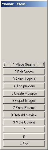
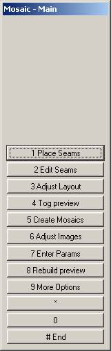
| 1. | The Mosaic Steps dialog shows the “Main Steps” that will be followed when creating the mosaics. |
| 2. | The standard MenuKeys dialog displays all commands that are available during the mosaicing process. NOTE: The Mosaic Steps dialog and the MenuKeys share common commands. Anything that can be selected from the Mosaic Steps dialog can also be selected using the MenuKeys dialog. While the Main Steps dialog only gives a few basic commands, and is meant to provide the user with a broad overview of the mosaic creation process, the MenuKeys dialog provides all available options at any given time. |
| 3. | The VrMosaic status dialog displays all images in the current project, grouped by strip numbers. This dialog provides a quick view of the mosaicing status, and can be used to set images as active or inactive, and as complete or incomplete. The Mosaic Status Dialog, One dialog shows the “Main Steps” that will be followed when creating the mosaics. The other dialog is a standard Vr MenuKeys dialog. The Main Steps dialog and the MenuKeys share common commands. Anything option that can be selected from the Main Steps dialog can also be selected using the MenuKeys dialog. While the Main Steps dialog only gives a few basic commands, and is meant to provide the user with a broad overview of the mosaic creation process, the MenuKeys dialog provides all available options at any given time. |
| 4. | The Overview graphics window (shown on the upper left) is used to display an overview of the active ortho images. Images in this window are display at their true geographic location. |
| 5. | The Layout graphics window (shown on the upper right) is used to display a layout view of the active ortho images. Images in this window are not displayed at their true geographic location, but are separated out so that the images do not overlap. |
| 6. | The Main graphics window (shown on the bottom) is used for detailed seam line creation and editing. |
NOTE: The view in all graphics window can be changed using standard VrOne zoom commands such as Zoom All, Page Up, Page Down, etc. There is only one active window at a time, but the cursor (or cursors in layout view) will track in all windows.
The picture shown below shows a typical screen layout after the Mosaic application has been started.
Local Commands
The following key-in commands are available while running the Mosaic application.
Key-in |
Description |
Range |
SHOWSTATUS |
Show status dialog |
N/A |
SHOWSTEPS |
Show steps dialog |
N/A |
SHOWOVERVIEW |
Show overview window |
N/A |
SHOWLAYOUT |
Show layout window |
N/A |
HOLD= |
Hold image number |
Number of image to hold when matching images. |
FEATHER= |
Feathering |
0=Feathering off 1=Feathering on |
FEATHERMODE= |
Feather Mode |
0=Use project feather width 1=Use Non-Graphics pointer |
FEATHERWDT= |
Feather width to use if FEATHERMODE=0 |
0-255 |
FEATHERADJONLY= |
Feather to adjacent images only |
0=No 1=Yes |
FEATHERALLCOLORS= |
Feather all colors or exclude pure black and pure white |
0=No 1=Yes |
WRITEPYRA= |
Write pyramids as images are created |
0=No 1=Yes |
COMP= |
Compress output images |
0=No 1=Yes |
COMPQUAL= |
Compression Quality |
0-100 |
OUTFIL= |
Default output file name |
Valid file name |
BACKCOLOR= |
Background color |
Color value |
PYRALEVEL= |
Output pyramid level |
0-6 |
SEGWDT= |
Set width of current segment. Only valid during seam placement. |
0-255 |
PARFIL= |
Load parameter file |
Valid file name |
TYPE= |
Output image type |
0=Same as first image 1=RGB 2=Greyscale |
SEAMLAY= |
Layer for seam lines |
1-10001 |
BATCHSHEETLAY= |
Layer for batch sheet lines |
1-10001 |
BATCHSHEETNAMELAY= |
Layer for batch sheet names |
1-10001 |
BATCHSHEETPATH= |
Path to output batch sheets |
Valid path name |
PREVEDIT= |
Preview mode on during editing |
0=No 1=Yes |
PREVMODE= |
Preview mode |
0=Clip only 1=Balance only 2=Clip and Balance |
SHOWIMGEDGES= |
Show image edges during editing |
0=No 1=Yes |
IMGEDGESPEN= |
Pen number to use when drawing image edges |
0-255 |
MATCH= |
Match images before output |
0=No 1=Yes |
HANDLESON= |
Display handles during editing |
0=No 1=Yes |
TICKSON= |
Display ticks during editing |
0=No 1=Yes |
HILITEMODE= |
Active segment hilite mode during editing |
0=Solid 1=Dashed |
HILITEPEN= |
Pen to use when hiliting segments during editing |
0-255 |
OVERLAP= |
Overlap amount for image layout |
Integer |
SIDELAP= |
Sidelap amount for image layout |
Integer |
SEPCHAR= |
Separator character between image strip and photo number |
0=None 1=Underline 2=Dash 3=Tilde |
NUMSTRIPCHARS= |
Number of characters in image name for strip number |
1-8 |
NUMPHOTOCHARS= |
Number of characters in image name for photo number |
1-8 |
MANUALPROMPT= |
Provide a prompt for image name and pixel size during manual output |
0=No 1=Yes |
Mosaic Application Windows
VrMosaic Main Steps Dialog
The following options are shown in the Main Steps dialog.
Main Steps Dialog
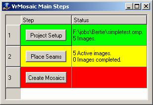
1. Define Project.
2. Place Seams
3. Create Mosaics
This is the main MenuKeys dialog that is display when Mosaic is first started.
Each of the three main steps has several options. Each step will be explained in detail below.
1. Define Project
Defining the project settings is the first step in the Mosaic process.
Selecting Project Setup from the main steps dialog, or selecting “7 Enter Params: from the MenuKeys dialog will display the project settings dialog box.
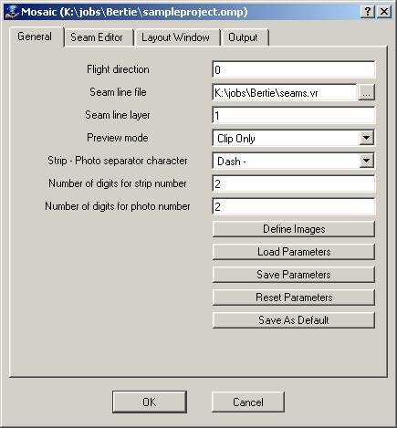
Project Dialog General Tab
Flight direction
Specifies the general angle of flight direction for the project. This is entered in degrees and represents a counterclockwise rotation from N-S or E-W. If the flight was flown close to N-S or E-W, then this can be left at 0. To calculate this value, first determine the orthogonal direction that is closest to your flight angle (either N, S, E or W), and then calculate an approximate delta rotation from the orthogonal direction to the flight direction. Enter this delta rotation angle as a positive number if the angle from the orthogonal direction to the flight direction is counterclockwise. Enter it as a negative number if the rotation is clockwise.
Seam line file
Enter a file to store the seam lines. This is a standard VrOne vector database file. The file will be created for you if it does not exist. This file may also contain any other data that you would like to have available while collecting the seam lines (such as sheet layout lines), however the layer you choose for “Seam line layer”should not have any other entities on it.
Seam line layer
This is the layer that all seam lines should be on. If seam lines are generated automatically, they will go on this layer.
Preview Mode
Specifies the mode to use when previewing mosaic images.
Clip Only |
During preview mode, images will be clipped at the seam lines. This will allow the user to see how the images fit together at the seam lines, but no tonal or color changes will be shown. |
Match Only |
During preview mode, images will be matched, and then displayed with tonal and color changes. Warning, this may significantly increase processing time when turning on Preview mode, or when starting the Edit Seams routine. |
Clip and Match |
During preview mode, images will be clipped and matched as explained above. |
Strip – Photo separator character
Mosaic uses the image filenames to determine the strip and photo number for each image. This information is important for depending how images relate to each other, and for displaying images correctly in the layout window. Select the character that separates the strip number from the photo number in the image filenames. This can be one of the following options.
None |
There is no separator between the strip and photo number. |
Underbar _ |
There is an underline bar (_) character between the strip and photo number. |
Dash - |
There is a dash (-) character between the strip and photo number. |
Tilde ~ |
There is a tilde (~) character between the strip and photo number. |
Number of digits for strip number
If there is no separator character between the strip and photo number in the image filenames, then you must specify how many characters occupy the strip number in the filenames.
Number of digits for photo number
If there is no separator character between the strip and photo number in the image filenames, then you must specify how many characters occupy the photo number in the filenames.
Define Images
Pressing this button display another dialog that allows you to define what images are part of this project.
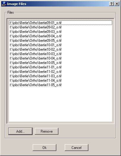
You can add or remove images from the image list. Pressing the Add… button display a standard image selection dialog where multiple images may be added to the project. Pressing the Remove button will remove any highlighted images from the project.
Save Parameters
Saves current parameters to an ASCII file. Displays a file save dialog box and prompts for an output file name. The default file extension is .omp.
Load Parameters
Loads parameters from a previously saved ASCII file. Displays a file open dialog box showing files with the .omp extension.
Reset Parameters
Resets current parameters to default values.
Save As Default
Pressing this button will save all of the current project settings as the defaults settings to be used when creating new projects. The specific images defined in the project are not included in the default settings.
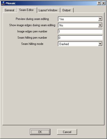
Project Dialog Seam Editor Tab
Preview during seam editing
If set to Yes, then image previewing will be on during seam line editing. The current Preview Mode will be used. With this on, it is possible to edit seam lines and instantly see how the images will fit together at the seam lines.
Show image edges during seam editing
If set to Yes, then image edges will be displayed as solid lines during seam line editing.
Image edges pen number
Pen number to use when drawing image edges during seam line editing.
Seam hiliting pen number
Pen number to use when hiliting seam lines during seam line editing. Seams lines are hilited as the cursor moves close to them during seam lines editing. The hiliting indicates which seam will be affected by the edit operation.
Seam hiliting mode
This can be set to "Solid" or "Dashed". This controls how the hiliting is displayed during seam line editing.
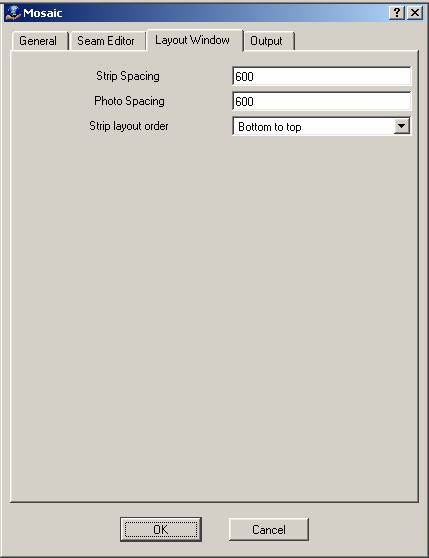
Project Dialog Layout Window Tab
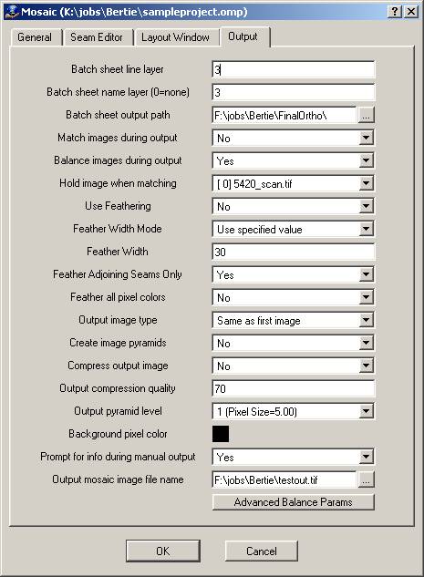
Project Dialog Output Tab
Batch sheet line layer
This is the layer that all sheet borders should be on. When using the batch output mode, sheet will be determined by looking for closed lines on this layer.
Batch sheet name layer
This is the layer that all sheet border file names should be on. If you want file names to be assigned incrementally based on the main output file name, then set this to 0. To control the file names that are used when outputting mosaic sheets in batch mode, place the file names (using VrOne text entities) inside each sheet border, and set this layer to match the layer of the file name labels.
Batch sheet output path
If a batch sheet name layer is specified, then the output files will be placed in this path directory.
Balance images during output
If set to Yes, then the balance adjustments will be applied while the images are written.
Hold image when matching
When creating the output mosaics, images are color matched to each other using the image overlap areas. The matching process will always pick one image that will remain unchanged, and match all other surrounding images to the unchanged image. Images that actually overlap the hold image will be matched first, then images that surround them will be matched. This cycle will continue until all images are matched.
Use Feathering
If set to Yes, then feathering will be used along seam lines. If set to No, then feathering will not be used.
Feather Width Mode
If set to "Use specified value", then the value specified in the "Feather Width" field will be used. If set to "Use non graphics pointer", then the value of the seam lines non graphic pointer will be used. NOTE: The width of individual segments can always be overridden.
Feather Width
Width to use when feathering (in pixels). This will only be used if Feather Width Mode is set to "Use specified value", and will be overridden if individual segments are assigned different widths.
Feather adjoining seams only
If yes, then only image data from adjoining seam lines will be used when feathering. If no, then all image data will be used. Previous versions always used all image data. Allowing all image data to be used is faster, but could cause problems with large overlaps.
Feather all pixel colors
If no, then pixels that are solid white or solid black will not be used when feathering. If yes, then all pixels will be used.
Output Image Type
Controls the color mode of the output image. This can be set to one of the following:
| • | "Same as first image" - If first image is RGB then output mosaic will be RGB. If first image is grayscale then output mosaic will be grayscale. |
| • | "Color" - Output mosaics will be RGB color. (24-bit) . |
| • | "Greyscale" - Output mosaics will be greyscale (8-bit). |
Create image pyramids
If set to Yes, then image pyramids will be created as the mosaic image is written. This will result is slightly longer processing times, but will eliminate the need for VrOne to create image pyramids the first time the mosaic is opened. If set to No, then old image pyramid files will be deleted, but new ones will not be created until the mosaic image is opened.
Compress output image
If set to Yes, then the output mosaic images will use JPEG compression, if set to No then the output images will not use compression. The output images will use this setting regardless of the file format of the input ortho images. The Output compression quality parameter should be set accordingly if this parameter is Yes.
Output compression quality
This is value from 0 to 100 that determines how much the output image will be compressed. Lower numbers result in greater compression but with more loss of image quality. Higher numbers achieve greater image quality with larger file sizes. A good default value is 70, providing a compression ratio around 8 to 1 for color images with minimal loss of quality.
Output pyramid level
This option allows the output mosaic images to be written out at different pixel size than the input ortho images. The output file sizes and image quality will decrease by powers of 2 for each higher pyramid level that is chosen. This option is useful for creating composite mosaics of very large areas that would require too much space if written out at full quality (pyramid level 1). This also provides a quick way to create “thumbnail” mosaic images of large areas. When selecting the output pyramid level, the resulting pixel size is displayed for informational purposes only. The pixel size computation is always based in the pixel size of the first opened ortho image in VrOne. The pixel size is read from the TIFF world file (.tfw).
Background pixel color
This option allows the output mosaic images to be written out at different pixel size than the input ortho images. The output file sizes and image quality will decrease by powers of 2 for each higher pyramid
Prompt for info during manual output
If set to Yes, then a dialog will be displayed each time a manual window is selected for image output. This dialog allows you to override the default output filename and pyramid level.
Output mosaic image file name
Defines the name of the output mosaic image file. This file will be overwritten if it already exists. An extension of .tif will be added to the filename if it is not specified. When using batch output mode, this file name will be used as the prefix for all output images.
Advanced Balance Params
This button is only displayed if you have purchased the VrBalance module. This allows advanced parameters to be set that affect the global image balancing process. The following dialog is displayed when this button is pressed
.
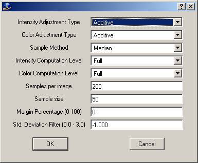
Intensity Adjustment Type
Sets the computation method to be used when adjusting the image intensity.
Additive mode seems to work best on the widest range of images, but there are some cases where multiplicative may give better results. Multiplicative mode will tend to increase the contrast of the images. Only try multiplicative if you are getting poor results with additive.
None |
Do not apply any intensity adjustment |
Additive |
Additive computation mode. |
Multiplicative |
Multiplicative computation mode |
Color Adjustment Type
Sets the computation method to be used when adjusting the image color.
Additive mode seems to work best on the widest range of images, but there are some cases where multiplicative may give better results. Multiplicative mode will tend to increase the contrast of the images. Only try multiplicative if you are getting poor results with additive.
None |
Do not apply any color adjustment |
Additive |
Additive computation mode. |
Multiplicative |
Multiplicative computation mode |
Sample method
Sets the method used when sampling data from the images
Mean |
Use the mean sample method. |
Median |
Use the median sample method. |
Intensity computation level
Sets the computation level used when computing the intensity adjustment. The medium setting doesn't try to fit the data as closely as full. In most cases, full is the best option, but if you have an image with a lot of lakes or other non-matching areas, medium might produce better results.
No adjustment |
No adjustment is applied to the intensity. |
Medium |
A medium computation is used. |
Full |
A full computation is used. |
Color computation level
Sets the computation level used when computing the color adjustment. The medium setting doesn't try to fit the data as closely as full. In most cases, full is the best option, but if you have an image with a lot of lakes or other non-matching areas, medium might produce better results.
No adjustment |
No adjustment is applied to the color. |
Medium |
A medium computation is used. |
Full |
A full computation is used. |
Samples per image
Sets the number of samples that are taken from each image. The default is 200. Increasing this value on very large images may produce better results because it will look at a larger percentage of the image. This has a direct relation on computation speed. Anything under 20 will probably not give reliable results.
Sample size
This is the square size of the area looked at for each sample. The default is 50, resulting in a 50x50 pixel sample.
Margin percentage
This controls how much of the outer image is ignored during processing. If your images have areas around the edges that contain invalid image data (such as fiducials), then this setting can be used to force those areas to be ignored. A value of 0 means do not ignore any image data, a value of 10 would ignore the outer 10% of the image.
Std. Deviation Filter
This setting limits the pixels to those that fall around the mode of the sample. For example, if set to 1.0 and the sample was a normal distribution, then only 66% of the data (around the middle value) would be used for the computation. This can be used to help filter out undesirable parts of an image.
0.0 = No filter
1.0 std = 66% of a normal distribution,
2.0 std = 95% of a normal distribution
3.0 std = 99.7% of a normal distribution)
2. Place Seams
Placing seam lines is the second step in the Mosaic process.
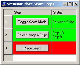
When the place seams button is pressed, the VrMosaic Place Seam Steps dialog is displayed.
And the Place Seams MenuKeys dialog is displayed.
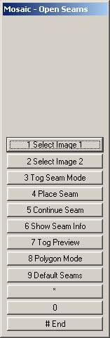
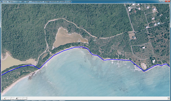
There are two basic seam types that can be used when defining seam lines. The first is referred to as an open seam, and is used to place a common line between two images or two strips. The second is referred to as a closed seam, and is used to define polygon shaped regions that identify areas of image data to be taken from single images. The two methods may be combined on any image. The majority of seam line placement is accomplished using open seams. Closed seams are normally used only to patch image data in specific areas.
Placing Open Seams
There are three main steps when placing open seam lines.
Step 1
The first step is to determine what mode to use when inserting the seam line. Seams may be inserted between strips or images. Selecting the “Toggle Seam Mode” button in the Steps dialog or activating “3. Tog Seam Mode” from the MenuKeys will toggle between strip mode and image mode. It is common practice to place the strip to strip seam lines before defining the image to image seam lines
NOTE: When in the strip mode, a single line should be placed for the entire length of the strip.
Step 2
The second step is to identify the images or strips that the seam line will be inserted between. This is done by using the mouse or digitizing device to point to images or strips in the Layout window. Because the Layout window displays the images without overlap, it is easy to identify individual images or strips.
If in Image mode, pressing the number 1 button while pointing to an image will cause it to be highlighted and set as Image 1. The next image over on the same strip will automatically be highlighted and set as Image 2. Pressing the number 2 button while pointing to an image allows you to identify Image 2 manually if it wasn’t correctly identifying by VrMosaic. Pressing the number 2 button while pointing to the image that was already identified as Image 1 will remove the selection of Image 2. This is useful for putting a seam line in that defines the edge of a single image that does not have another image beside it.
If in Strip mode, pressing the number 1 button while pointing to any image in a strip will cause that strip to be highlighted and set as Strip 1. The next strip over will automatically be highlighted and set as Strip 2. Pressing the number 2 button while pointing to an image in a strip allows you to identity Strip 2 manually if it wasn’t correctly identifying by VrMosaic. Pressing the number 2 button while pointing to an image in the strip that was already identified as Strip 1 will remove the selection of Strip 2. This is useful for putting a seam line in that defines the edge of a strip that does not have another strip beside it.
Step 3
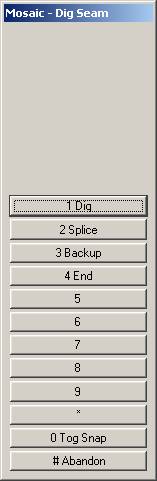
The third step is to insert the seam line. Selecting the “Place Seam” button in the Steps dialog, or using “4. Place Seam” from the MenuKeys will start the seam placement process. The following MenuKeys dialog is displayed.
At this point the main graphics window (Window 1) should be used to digitize points along the seam line. The graphics window can be zoomed in as close as needed, while the Overview window can be left at a higher zoom level to monitor where the seam line falls within the overlap area. The images will automatically update as the seam line is placed, showing you exactly how the seam line is affecting the images.
NOTE: When placing strip to strip seam lines, you will not see all of the images in the strip at first. The images will appear as needed while you continue to place the seam line along the strip to strip overlap area.
When the seam line is complete, use the “4. End” command to save the seam line. This saves the seam line in the current VrOne file, and returns to the Define Seams MenuKeys dialog. VrMosaic will automatically select the next two image or strips, and they will be highlighted in the Layout window. If these are the next two images or strips that you want to place a seam line between, then you can repeat Step 3 and digitize a new seam line. If not, you can use steps 1 and 2 as needed to identify the correct images and strips, and then place the next seam line.
Placing Closed (Polygon) Seams
There are three main steps when placing closed seam lines. Closed seam lines are only assigned to a single image. This is useful for taking individual features from a specific image to use in the mosaic output.
Step 1
Select “8. Polygon Mode” from the Define Seams MenuKeys dialog. This will display the following MenuKeys dialog.
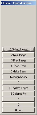
Step 2
The second step is to identify the image that the seam line will be assigned to. A default image will already be highlighted in the Layout window. If this is not the image that you want to use, then use the mouse or digitizing device to select a different image in the Layout window. Because the Layout window displays the images without overlap, it is easy to identify individual images. The image will be highlighted and set as the Image that the seam line will be assigned to.
Step 3
The third step is to insert the seam line. Selecting “4 Place Seam” from the MenuKeys will start the seam placement process. The following MenuKeys dialog is displayed.
At this point the main graphics window (Window 1) should be used to digitize points along the seam line. The graphics window can be zoomed in as close as needed, while the Overview window can be left at a higher zoom level to monitor where the seam line falls within the image.
When the seam line is complete, use the “4. End” command to save the seam line. This saves the seam line in the current VrOne file, and returns to the Define Seams MenuKeys dialog. VrMosaic will automatically select the next image, and it will be highlighted in the Layout window. If this is the next image that you want to place a seam line on, then you can repeat Step 3 and digitize a new seam line. If not, you can use step 2 to identify the correct image, and then repeat Step 3 to place the next seam line.
3. Create Mosaics
Creating the final mosaic output image is the third step in the Mosaic process.
When the Create Mosaics button is pressed, or the VrMosaic Place Seam Steps dialog is displayed.
Press the “Create Mosaics” button in the Main Steps dialog or use “5. Create Mosaics” from the MenuKeys to start the Mosaic creation step. This will display the following MenuKeys dialog.
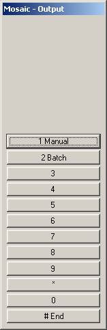
Manual
Choose option “1. Manual” to manually select a single output window. The following Menukeys dialog will be displayed.
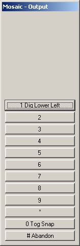
Select the lower left hand corner of the output window. The following MenuKeys dialog will then be displayed.
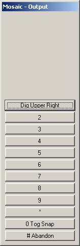
As the cursor is moved, a box representing the output area will display in the graphics window. The VrMosaic main window will also display the width, height, and approximate file size of the output image, and the output pyramid level.
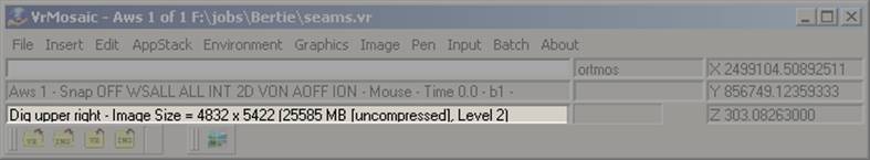
Select the upper right hand corner of the output window.
If the manual prompt mode is not on, then the following MenuKeys dialog will be displayed.
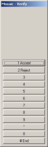
If you choose the “1. Accept” option, a single output image will be created using the name defined in the “Output mosaic image file name” parameter. A “scanline” will be displayed in the graphics window representing the progress as the output image is created.
If you choose “2. Reject”, you will be returned to the “Dig Lower Left” MenuKeys dialog.
If the manual prompt mode is on, then the following dialog will be displayed:
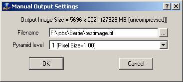
At this point you can override the default project settings for Output filename and Pyramid level. The new settings will be saved back to the project. If you press OK, the output image will be created using the filename and pyramid level specified. A “scanline” will be displayed in the graphics window representing the progress as the output image is created.
Batch
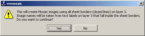
Choose option “2. Batch” to create multiple mosaic output images in batch mode. This option requires an existing sheet layout in the current workspace. The sheet layout consists of closed lines containing text labels that represent the output image names. These sheets may be define using VrOne or VrMosaic using standard commands such as Insert Line and Insert Text.
The following dialog will be displayed. This lets you know where the Mosaic application will look to find sheet lines and sheet labels. In this case, the parameters were defined so that sheet borders and sheet labels (image names) would both be on layer 3.
If you chose to continue, VrMosaic will find all of the output sheet borders and names that have been defined and display them in the following dialog.
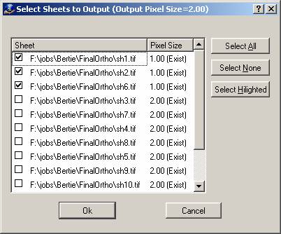
This dialog can be used to select any combination of sheets to output. Sheets that do not exist yet, or sheets that do exist but have a different pixel size, will be automatically selected for output.
When the Ok button is pressed the output process will begin. VrMosaic will balance the images, apply seam line cuts and feathering, and cut out images into the provided sheet layout. Depending on the size and number images, this process can take from several minutes to several hours to run.
Miscellaneous Menu Keys Options
This section documents MenuKey options that were not included as part of the main Mosaic process documentation.
Main Menu Keys dialog box
Place Seams |
Displays Place Seam MenuKeys |
Edit Seams |
Displays Edit Seam MenuKeys |
Adjust Layout |
Displays layout adjustment MenuKeys |
Tog preview |
Toggle preview mode on/off. If seam lines have been placed, then this will toggle whether images are displays in preview mode (clipped and balanced), or in standard mode (original images). |
Create Mosaics |
Displays create mosaic MenuKeys |
Adjust Images |
Display image adjustment dialog for controlling image brightness and contrast. |
Enter Params |
Display project settings dialog. |
Rebuild preview |
Rebuilds image preview. Some edit operations may result in a state where preview mode does not display the latest changes. This option will rebuild the image previews from the current seam lines. |
More Options |
Displays the More Options MenuKeys. |
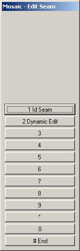
Edit Seam Menu Keys dialog box
Id Seam |
Use mouse button 1 to select an existing seam line to enter single seam editmode |
Dynamic Edit |
Displays the Dynamic Edit MenuKeys dialog, allowing all seams to be edited dynamically. |
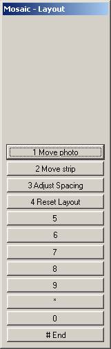
Adjust layout Menu Keys dialog box
Move Photo |
Displays the Move Photo MenuKeys, allowing a single photo to be moved to a new location in the layout window. |
Move Strip |
Displays the Move Strip MenuKeys, allowing a strip of photos to be moved to a new location in the layout window |
Adjust Spacing |
Display a dialog that allows a horizontal and vertical spacing factor to be entered allow the images to easily be spread apart of pulled together in either direction. |
Reset Layout |
Resets the images to their original layout positions. |
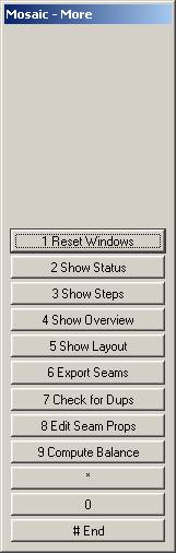
More Options Menu Keys dialog box
Reset Windows |
Resets the main Mosaic display windows to default locations. |
Show Status |
Displays the Mosaic status dialog if it has been closed. |
Show Steps |
Displays the Mosaic steps dialog if it has been closed. |
Show Layout |
Displays the Mosaic overview window if it has been closed. |
Show Steps |
Displays the Mosaic layout window if it has been closed. |
Export Seams |
Placing all seams as closed polygons on a user-defined layer. |
Check for Dups |
Checks for duplicate seam lines (more than one seam line on the same side of an image). Normally there should be only one seam line representing a particular side of an image. If more than on is found, there is probably a problem with the seam line collection. |
Edit Seam Props |
Allows a single seam line to be selected, and edited using a dialog box to change the seam line properties. |
Compute Balance |
Global image balancing is a two-step process. The first step is computing the balance parameters by comparing all images in the project. The second step is applying the balance adjustments during image output, or during preview display mode. Normally the first step is completed automatically the first time balance parameters are needed by VrMosaic. Once balance parameters are computed, they are not computed again unless the list of images in the project is changed. You can use this to force the balance parameters to be re-computed even if the list of images did not change. |