Vr Mapping |
ON-LINE REFERENCE DOCUMENTATION CARDINAL SYSTEMS, LLC |
Vr Ortho
Type: Stand-alone Application (vrortho.exe)
Orthophoto Generation Application.
Orthophoto
This application creates ortho rectified images from multiple raw input images. VrOrtho accepts TIFF, JPEG, MrSID, and JPEG200 image formats as input and outputs images in TIFF or JPEG format.
The ortho rectification process transforms standard perspective images without uniform scale into geographically referenced images with the perspective removed to provide uniform scaling. The ortho images contain geographic referencing in the form of TIFF world files with a .tfw extension, GeoTIFF tags inside a TIFF file, or as JPG world files with a jgw extension. The world files and GeoTIFF tags contain the ground coordinates in the upper left corner of the image and a pixel size in ground units for the x and y direction. When used on a standard aerial mapping job, the ortho process results in a series of overlapping ortho images. The ortho images can then be brought into a mosaicing application such as VrMosaic to tie the orthos together into a seamless image mosaic.
In order to perform the ortho rectification process, VrOrtho must have a DTM ground surface for the area to be rectified and must have images that have been fully oriented. The DTM ground surface may be computed from standard VrOne vector files, containing points and break lines, or may be loaded from a VrOne surface file. If the DTM ground surface is specified as a VrOne vector file with points and break lines, the surface will be computed as needed directly from the VrOne file(s). If a surface file is used, the surface is loaded directly from the file, potentially saving a significant amount of processing time.
The image orientation process may be performed completely inside VrOrtho or it can be imported from other sources. The two required orientation steps are interior and exterior orientation. Interior orientation is the calibration of images to known fiducial locations. Interior orientation is available inside Image Utility, VrTwo orientation, and VrOrtho. When dealing with large numbers of images, Image Utility provides a method for automatic interior measurement. VrOrtho automatically recognizes interior orientations that have been performed with VrTwo orientation or Image Utility. Exterior orientation is camera station location and rotation for each image. Exterior orientations can be imported from VrTwo Orientation or Aerial Triangulation software or may be computed inside VrOrtho using single image resection. Single image resection consists of identifying at least 3 known ground location in the image; a ground control file is required for this step.
Once the images have been orientated and a ground surface defined, VrOrtho is ready to generate the output ortho images. This process is done in a batch mode, where one or more input images are selected and a single output ortho image is created for each input image. By default, each output ortho image covers the entire area of its corresponding input image. In many cases, the raw input images will have unneeded image data around the edges of the image. It is possible to change the default settings to eliminate the extra image data so the output orthos only contain the relevant portion of the input image. If the ortho images will be used in a mosaicing process, the ortho areas should be defined so that there is sufficient overlap between adjoining images.
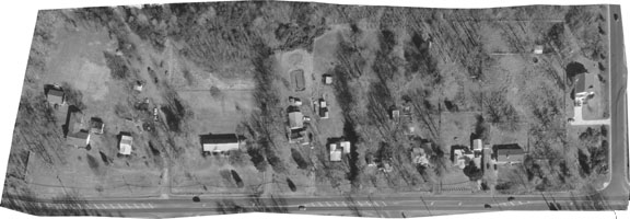
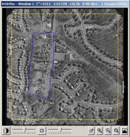
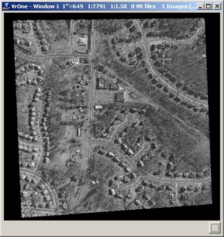
The image on the left below shows a typical aerial image with fiducials and data strip information on the outside of the image. The yellow line encloses the area that will be used when creating the final ortho image after changing the VrOrtho default settings to eliminate extra image information. The image on the right is the output ortho image created from the input image.
In addition to using default settings to define the ortho areas for the images, VrOrtho also provides a ortho area editing application that allows a user-defined ortho area for each input image. Using the ortho area editor, any portion of the input image may be selected, included polygon shaped areas.
Before creating the final ortho images there are several output options to consider. These include the output pixel size in ground, background colors, and handling of pixels that fall outside the DTM surface area. These options are discussed in more detail in the reference section.
Here is a sample work flow using Vr Mapping software to ortho images:
1. Obtain raw photos in digital form.
2. Create a new project using VrOrtho, define project settings, and add raw photos to project.
3. Perform interior orientation on images using VrOrtho if they have not already been oriented.
4. Perform exterior orientation on images using VrOrtho single photo resection or by importing exterior orientation data.
5. Define ortho areas using default settings or by using ortho area editor.
6. Define output pixel size.
7. Create ortho images.
8. The ortho images are now ready to be used by the VrMosaic application to define seam lines and create final output mosaic images.
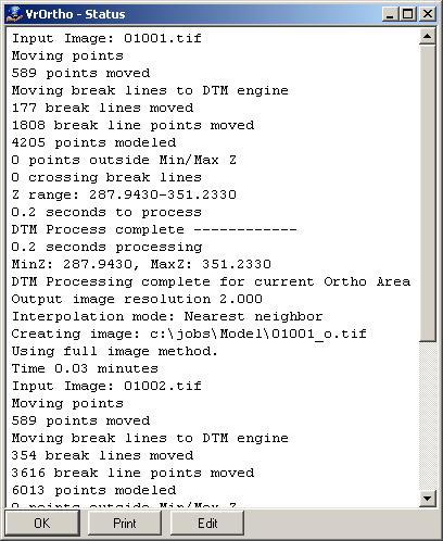
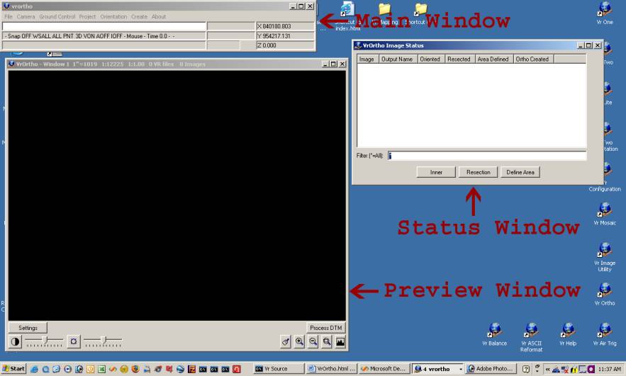
VrOrtho will start by opening the Main Window, the Ortho preview window, and the ortho status window.
Starting an Application (Command)
Start commands by pulling down a menu and selecting an item. Alternatively, start commands with a key-in using the command name. Each command's key-in is listed in parentheses in the pull down menu after the command.
The Main Window
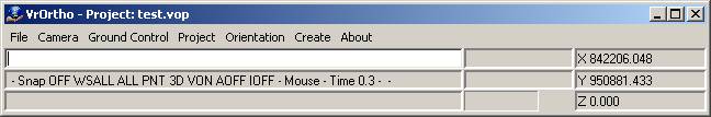
The Main Window in VrOrtho contains the command pull down menus, a key-in area, two information areas, a progress bar and the coordinate display.
Command names may be typed into the key-in area at almost any time.
On the border of the Main Window is the active project.
The Image Status Window
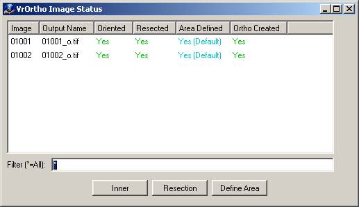
The Image Status window displays a current status for each input image. This window can also be used to start the Interior, Orientation, Single Image Resection, and Define Ortho Area commands by highlighting a single image and pressing the appropriate button.
The Ortho Preview Window
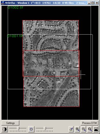
The Ortho Preview Window displays a preview of the output ortho image areas and, if they have been generated, of the ortho images. This window can be used to quickly verify that ortho areas are defined correctly. The original input image bounds and the DTM surface boundary are also displayed. The “Process DTM” can be used to force the currently defined DTM surface to be processed, allowing the DTM boundary to be displayed. This window may be used to zoom and pan around the image outlines. Use the Page Up and Page Down keys to zoom in and out. Use the arrow keys to pan. The icons in the lower right corner of this window may also be used for zooming.
Pressing the “Settings” button causes the following dialog to display:

Show Output Ortho Images
Displays the ortho images in the preview window.
Show Input Image Names
Displays the input image names in the upper left corner of each input image boundary.
Pen number for Image Edges
Controls the color used to display the input image boundaries. The color is taken from the currently configured pen table for VrOne.
Pen number for Image Names
Controls the color used to display the input image names. The color is taken from the currently configured pen table for VrOne.
Pen number for Ortho Areas
Controls the color used to display the output ortho areas. The color is taken from the currently configured pen table for VrOne.
Pen number for DTM Boundary
Controls the color used to display the DTM boundary lines. The color is taken from the currently configured pen table for VrOne.
Project setup consists of creating a new project file and defining the project parameters. The steps to take before starting a project vary based on how the image orientation is to be defined. If a camera definition file has not yet been defined, it should be created using Camera->New Camera. If importing interior orientations form VrTwo or Image Utility, a camera file should already exist.
If importing exterior orientations, no other steps are required before starting the project. If single image resection will be used to compute exterior orientations, a coordinate file must be defined. If a VrOne-compatible coordinate file (.cor extension) is not already available, one can be created using the Ground Control->New Coordinate File command.
The new ortho project is created by selecting Project->New Project. See command reference for detailed explanations of project settings.
After the project setup has been completed, use Create->Create Orthos to generate the output ortho images.
File Menu
Open Status Window
Opens the Image Status window if it is closed.
Open Overview Window
Opens the Ortho Overview window if it is closed.
Create Image Pyramids
Allows image pyramids to be created in batch mode. Image pyramids are stored for each image displayed by Vr Mapping software. The image pyramids provide overviews at different image resolutions, allowing fast image display at all zoom levels. Normally, image pyramid are created as needed by VrOrtho and this option should not need to be used.
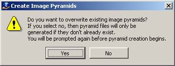
Select whether or not existing pyramid files should be overwritten with new files. This is useful if the image pyramids are outdated or corrupted. The following dialog is then displayed.
Exit
Exits VrOrtho.
Camera Menu
New Camera
Displays a dialog box to create a camera definition file.

Use the camera calibration data to enter all information about the camera being defined. Each input image in the VrOrtho project is assigned to a camera file (usually, all images in a single project will share a single camera file).
Edit Camera
Displays a dialog box to select a camera definition file.
New Coordinate file
Displays a dialog box to create a coordinate file.
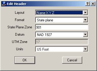
Select the desired layout format and units for the ground control file. The default settings are typically suitable. After these settings are defined, the coordinate definition dialog will display.
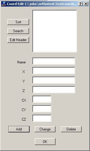
Use this dialog to define any ground control points that fall on the images being orthoed.
Edit Coordinate file
Displays a dialog box that allows a coordinate file to be selected.
New Project
Displays a dialog box to create a project file.
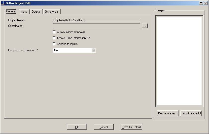
The right side of the dialog displays the current project's input images. These images may be defined in VrOrtho using the "Define Images…" button, or the list of images may be imported from an Image Utility project.
The following dialog is displayed if “Define Images…” is pressed.
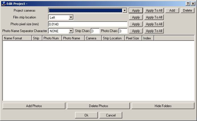
Pressing “Add Photos” displays a dialog to select and add one or more images to the project. Pressing "Delete Photos” deletes all currently highlighted photos. Pressing “Hide Folders” hides the folder locations of the image and camera names. The “Hide Folders” button changes to “Show Folders” when pressed, and then can be used to display the folder locations again.
To define a setting for all images, set the appropriate value then press “Apply To All” next to the setting. To define a setting for an individual image or images, highlight the image(s) first then press “Apply” next to the setting. The currently defined settings are applied to new photos as they are added to the project.
| • | Project cameras – Multiple cameras may be defined for a project. Use the “Add” button to add cameras to the project (the camera definition file must already exist). Use “Delete” to remove the currently highlighted camera from the project. |
| • | Film strip location – The image film strip location can be set to Left, Right, Top, or Bottom. |
| • | Photo pixel size (mm) – Defines the pixel size in millimeters for the image. |
| • | Photo Name Separator Character, Strip Chars, Photo Chars – These three settings define how the image name is interpreted to produce a Strip and Photo number. |
“Import ImageUtil…" prompts the user to select an existing Image Utility (.iup) file. All input images defined in the Image Utility project are imported into the VrOrtho project. “Define Images…” can be used to verify that the images have been imported with the correct settings.
The project dialog is divided into four tabs: General, Input, Output, Ortho Area.
General Tab
The general tab shows general project settings.
Project Name
Displays the file name for the current project.
Coordinates
Displays the coordinate file for the current project. This can be left blank if importing exterior orientations.
Auto minimize windows
Specifies whether to minimize all VrOrtho windows when ortho processing begins. The percentage complete will be displayed on the minimized taskbar button. If VrOrtho is running with Windows XP, taskbar button grouping may need to be disabled for the status to be visible.
Create ortho information file
Specifies whether an ortho information file should be created for each ortho image. This file will have the same name as the ortho image but will have a .voi extension. The information file is an ASCII file with information about the processing parameters used to created the ortho image (resampling mode, DTM source, etc.).
Append to log file
Specifies whether to append to the vrortho.log file after each run. Otherwise, the log file will be cleared each run.
Copy inner observations
Specifies whether an image with no observations should inherit the observations from the first image in the image list.
Input Tab
The input tab shows input data settings.
Use DTM Surface file
Specifies whether a surface file should be used for the DTM surface during ortho generation.
DTM Surface file
Defines the DTM surface file to use instead of reading the VrOne DTM data if "Use DTM Surface File" is enabled. This can result in much faster DTM processing times.
Create surface file if it does not exist?
Creates the DTM surface file from the VrOne vector data the first time the DTM surface is processed. This is only relevant if "Use DTM Surface File" is enabled. DTM source data must be available.
DTM Source
Defines the source data to use when generating the underlying DTM surface. The options are as follows:
| • | Vr Files - Use the “…” button to display the files selected. Use the "Add" and "Remove" buttons to add or remove VrOne vector files to or from the list. |
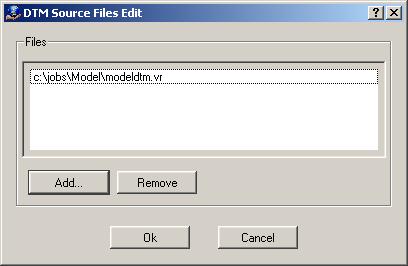
| • | Control Points - Uses all points in the project control file as the DTM surface. |
| • | Approximate Z - Uses a single elevation for the entire DTM surface. The elevation is taken from the “Approximate Z” value on the Output tab. |
DTM Extents
Defines how much of the DTM area to compute when creating orthos. This is only when not loading a surface file. If set to full, the entire input DTM area is computed. This will only be computed once before ortho output begins. If set to Ortho area only, only the area needed for the image being processed will be computed. A new surface will be computed for each output ortho image.
DTM Points layer(s)
Defines the VrOne layers that contain points to be used for the computation of the DTM surface.
DTM Breaklines layer(s)
Defines the VrOne layers that contain break lines to be used for the computation of the DTM surface.
Input minimum Z
Defines a minimum Z value for points to be added to DTM. This does not apply when reading an existing surface file.
Input maximum Z
Defines a maximum Z value for points to be added to DTM. This does not apply when reading an existing surface file.
Excluded points file
Defines file to which excluded points should be written. Formatted one per line with comma separation.
Import VrOne Dtm Params
Allows the import of a .dtm parameter file saved in VrOne or VrTwo.
Output Tab
The output tab shows ortho image output settings.
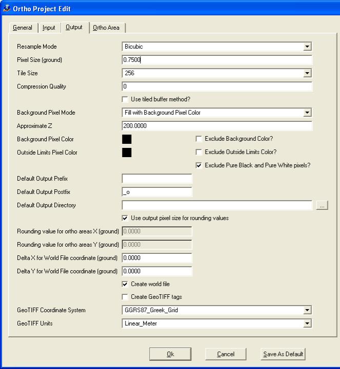
Resample Mode
Specifies the resample mode used to create the output orthophoto. Bicubic is the slowest, but typically results in the best output image.
Pixel Size (ground)
Defines the pixel size of the output orthophoto in ground units. It does not have to be the same size as the input photo pixel size.
Tile Size
Defines width and height of the tiles in output TIFF images. Options are “None”, “32”, “64”, “128”, “256”, or “512”. Set to “None” to produce non-tiled TIFF images.
Compression quality
Defines how much the output image will be compressed. Expressed as a value from 0 to 100. Lower numbers result in greater compression and more loss of image quality. Higher numbers achieve greater image quality and larger file sizes. A good default value is 70, providing a compression ratio of ~8:1 for color images with minimal loss of quality.
Use tiled buffer method?
Specifies whether small chunks of data should be processed at a time.Check this option if memory is limited and large rotated raw images are being processed. When images are rotated near 45 degrees, they sometimes require too much memory to work with the normal VrOrtho resampling methods (Full Image or Window Mode). Using tiled buffer method avoids memory problems but can be significantly slower than other methods. If this is not checked, Full Image or Window mode will be used automatically.
Background Pixel Mode
Specifies what action to take when a pixel to be resampled falls outside the DTM area. Either the “Approximate Z” will be assigned and the pixel will be resampled or the target pixel will be assigned the value specified in the “Background Pixel Color”.
Approximate Z
Defines the elevation to use for pixels that fall outside the DTM area during resampling if the Background Pixel Mode is set to "Use approximate Z value".
Background Pixel Color
Specifies the pixel (color) value to use for pixels that fall outside the DTM area during resampling if the “Background Pixel Mode” is set to “Fill with Background Pixel Color”.
Exclude Background Color?
Specifies whether valid image pixels that are the same color as the Background pixel color should be written with a slightly different color. This is useful when blending with VrMosaic.
Outside Limits Pixel Color
Specifies the pixel (color) value to use for a new pixel that falls outside the ortho limits during resampling. This may occur if the ortho area is defined by a polygon.
Exclude Outside Limits Color?
Specifies whether valid image pixels that are the same color as the Outside Limits pixel color should be written with a slightly different color. This is useful when blending with VrMosaic.
Exclude Pure Black and Pure White pixels?
Specifies whether valid image pixels that are the pure black or pure white should be written with a slightly different color. This prevents image pixels from being viewed as background pixels during mosaic processing.
Default Output Prefix
Defines prefix to be added to the beginning of each default orthophoto output file name.
Default Output Postfix
Defines postfix to be added to the end of each default orthophoto output file name.
Default Output Directory
Defines directory into which to place all ortho output files. If left blank, ortho output files will be placed in the project directory.
Use output pixel size for rounding values
Specifies whether the upper left corner of each ortho image should be aligned to an even interval of the output pixel size. This ensures proper alignment during mosaic processing.
Rounding value for ortho areas X (ground)
Defines value to which the lower left and upper right X values of each ortho area should be rounded. Set to zero for no X rounding.
Rounding value for ortho areas Y (ground)
Defines value to which the lower left and upper right Y values of each ortho area should be rounded. Set to zero for no Y rounding.
Delta X for World File coordinate (ground)
Defines value to apply to the upper left corner X of the World File. The World File is generated when an orthophoto is created. Set to zero to leave the coordinate unchanged.
Delta Y for World File coordinate (ground)
Defines value to apply to the upper left corner Y of the World File. The World File is generated when an orthophoto is created. Set to zero to leave the coordinate unchanged.
Create world file
Specifies whether an external .tfw world file should be created with each output TIFF image. The .tfw file contains georeferencing information for the ortho image and is supported by most mapping applications.
Create GeoTIFF tags
Specifies whether georeference information should be added internally to the output TIFF images using the GeoTIFF tag format. This format is supported by most mapping applications.
GeoTIFF Coordinate System
Sets the coordinate system information tag so other applications can automatically detect the coordinate system used by the image. Applies when VrOrtho is using GeoTIFF tags.
NOTE: This does not change the actual georeferencing information of the ortho image and is for informational purposes only. VrOrtho does not use the coordinate system of the data it is processing and does not verify that this setting is correct.
GeoTIFF Units
Sets the coordinate system units tag so other applications can automatically detect the units used by the ortho image. Applies when VrOrtho is using GeoTIFF tags.
NOTE: This does not change the actual units of the ortho image and is for informational purposes only. VrOrtho does not use the units of the data it is processing and does not verify that this setting is correct.
Ortho Area
The output tab shows ortho area settings.
Z Source for Ortho Area Editor
Specifies how to determine cursor Z position. "DTM" computes a DTM surface for the image being used., resulting in a more accurate cursor location in the ortho area edit but slower processing times when entering the editor. “Approx Z” uses the current Approximate Z to compute the cursor location, leading to a less accurate cursor location but quicker editor start-time.
DTM Area for Ortho Area Editor
Specifies the area for which the DTM surface should be formed. “Full” forms a DTM surface from the entire DTM extents. This does not affect the DTM surface used when creating the final output orthos. The DTM surface is not recalculated for each image that is displayed in the ortho area editor. “Image Extents” forms a DTM surface from the entities within the current image extents. The DTM surface is recalculated for each image that is displayed in the ortho area editor.
Extents mode for default ortho area
| • | Image - Ortho area covers the entire image extents. |
| • | Fiducials - Ortho area is defined by the four corner fiducial positions. |
| • | Centered - Ortho area is centered around the perspective center of photo and aligned to ground coordinate system. |
If "Image" or "Fiducials" mode is selected, the following options will be available:
Default ortho area left margin (pixels)
Determines how far right to move the left side of the default ortho area extents. This only affects ortho areas defined by default (not selected by the user).
Default ortho area right margin (pixels)
Determines how far left to move the right side of the default ortho area extents. This only affects ortho areas defined by default (not selected by the user).
Default ortho area top margin (pixels)
Determines how far down to move the top side of the default ortho area extents. This only affects ortho areas defined by default (not selected by the user).
Default ortho area bottom margin (pixels)
Determines how far up to move the bottom side of the default ortho area extents. This only affects ortho areas that are defined by default (not selected by the user).
If "Centered" mode is selected, the following options will be available:
Default ortho area size along negative X axis (ground)
Determines how far to extend the ortho area along the negative X axis starting at the perspective photo center. This only affects ortho areas defined by default (not selected by the user).
A Default ortho area size along positive X axis (ground)
Determines how far to extend the ortho area along the positive X axis starting at the perspective photo center. This only affects ortho areas defined by default (not selected by the user).
Default ortho area size along negative Y axis (ground)
Determines how far to extend the ortho area along the negative Y axis starting at the perspective photo center. This only affects ortho areas defined by default (not selected by the user).
Default ortho area size along positive Y axis (ground)
Determines how far to extend the ortho area along the positive X axis starting at the perspective photo center. This only affects ortho areas defined by default (not selected by the user).
Contour Interval
Defines the contour interval to use when displaying contours in Ortho Area Editor.
Contour Index Interval
Defines the contour index interval to use when displaying contours in Ortho Area Editor. Index contours are displayed in a different color than other contours.
Select VrOne display Files
Any VrOne files selected are displayed on top of the images in the Ortho Area editor. This is useful for seeing where defined seam lines fall on the images.
VrOne display layer(s)
Specifies which VrOne layers contain entities to be plotted during ortho area editing.
Open Project
Displays a dialog box to open an existing project file. If a project is already open, it will be closed before the new one is opened.
Edit Project
Displays a dialog box to edit the project settings. See New Project for details.
Change Project Location
Changes the project file location when the project files are moved from one directory or drive to another. A dialog will be displayed to select an existing VrOrtho project file. Once the file is selected the following dialog is displayed.
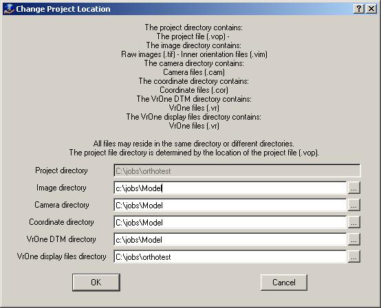
Enter the new directory locations for the items displayed and press "OK". If the directory locations were entered correctly, the project should now open without any problems.
Orientation Menu
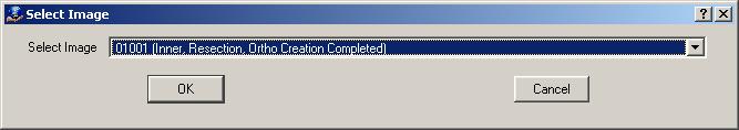
Inner Orientation
Displays a dialog box to select a single image on which to perform manual inner orientation. All project images will be available in the dropdown menu. A status for each image will also be displayed.
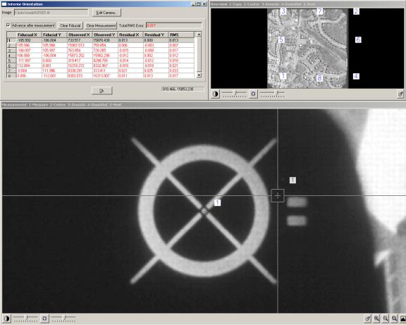
After an image is selected, the single image inner orientation application is displayed. Either the display icons or standard VrOne zoom keys (PgUp, PgDn, Direction Arrows) can be used to find and measure each fiducial. Single image inner orientation displays three windows: the status, overview, and measurement windows
The Status Window
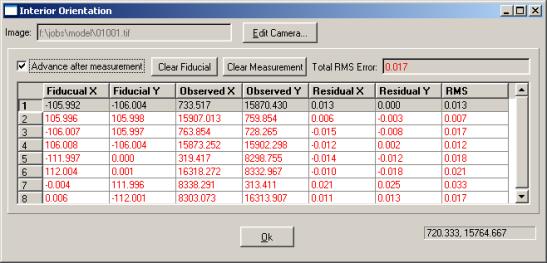
Displays the name of the image being measured and a table of all fiducial measurements.
The row for the fiducial currently being measured will be highlighted. Clicking on any row in the table makes that fiducial current and causes the measurement window to zoom to that fiducial.
| • | Edit Camera… - Displays a dialog box to edit the current camera definition. |
| • | Advance after measurement – Specifies whether measuring a fiducial should cause the next highest fiducial number to become current. The measurement window will zoom to the next fiducial. |
| • | Clear Fiducial – Sets the X and Y location for the currently highlighted fiducial to 0.0. This removes the fiducial from the inner orientation process. |
| • | Clear Measurement – Clears the measurement for the currently highlighted fiducial. |
| • | Total RMS Error – Displays the Total RMS Error based on the currently measured fiducials. This is updated in real-time. |
The Measurement Window
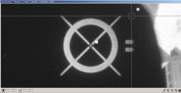
Allows measurement of fiducials. A fiducial is measured by placing the cross hairs over the center of the fiducial and clicking the left mouse button. If a fiducial has already been measured, a cross and a number are displayed indicating the measurement location and the fiducial number.
The Overview Window
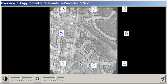
Displays the entire image with fiducial number labels. Pressing the left mouse button causes the window to zoom to the region below the square mouse cursor. The Page Up and Page Down keys change the size of the zoom window.
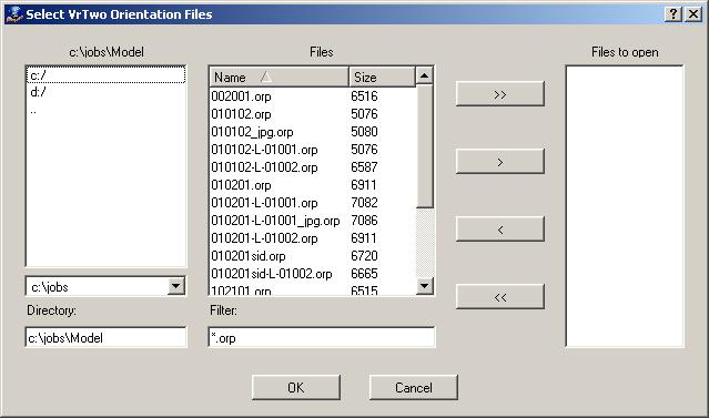
Import VrTwo Orientation
Displays a dialog box where a Vrtwo orientation can be imported. VrTwo orientation files have .orp extensions and are saved using the model names defined in VrTwo orientation. Multiple .orp files can be imported at once.
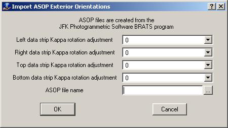
Import Exterior Orientations->ASOP - JFK
Displays a dialog box where exterior orientation can be imported from ASOP – JFK files.
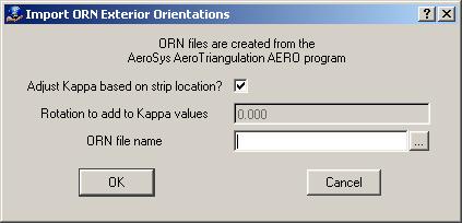
Import Exterior Orientations->ORN - Aerosys
Displays a dialog box where exterior orientation can be imported from ORN - Aerosys files.
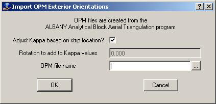
Import Exterior Orientations->OPM - Albany
Displays a dialog box where exterior orientation can be imported from OPM – Albany.
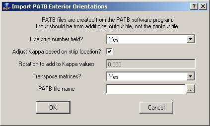
Import Exterior Orientations->PATB
Displays a dialog box where exterior orientation can be imported from PATB files.
Set Ortho Area
Displays a dialog box to select a single image to be displayed in the ortho area editor. The ortho area editor is a tool to visually define the area to be extracted from an input image. When the ortho area editor is entered for the first time for an image, the default area is displayed based on the project settings. If the ortho area is changed while in the editor, it will be saved and used when the ortho is created. This provides a way to rectify small or irregularly shaped areas from images.

After an image is selected, the following windows display.
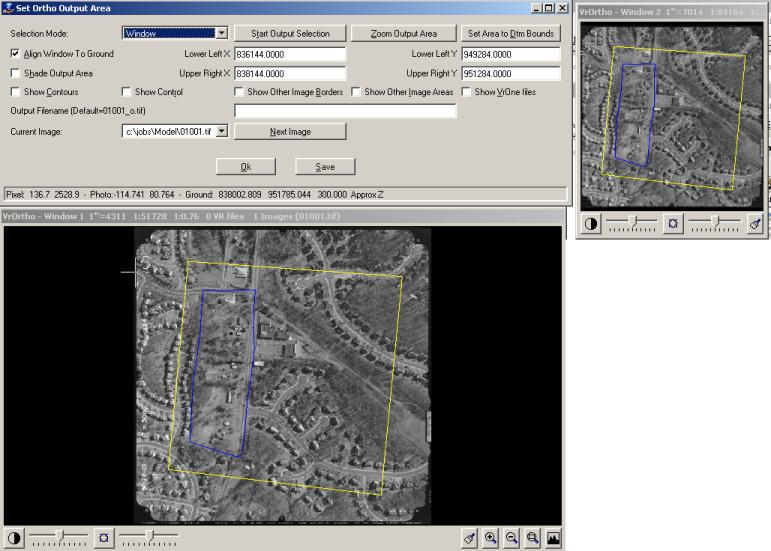
The top left dialog box contains the main options for defining the current ortho area. The upper right window is an overview of the entire image. The lower left window is the measurement window. The overview and measurement windows have display icons to change brightness and contrast, zoom, and pan. The standard VrOne zoom keys (PgUp, PgDn, Direction Arrows) can also be used to zoom and pan.
Settings Window
Selection mode
Changes the selection mode. The area can be defined as a window or a polygon.
Start Output Selection
Defines the ortho. If "Window" selection mode is on, the following menu keys dialog is displayed.
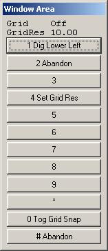
Use the left mouse button to digitize the lower left corner of the desired ortho area. The prompt will change to display "Dig upper right". Use the left mouse button to digitize the upper right corner of the ortho area. To align the ortho area to an even grid, select “0. To Grid Snap” or press F11 to toggle grid snap mode. The grid spacing can be controlled by selecting “4. Set Grid Res” or by pressing F4.
If "Polygon" selection mode is on, the following menu keys dialog is displayed.

Use the left mouse button to digitize the points that define the polygonal ortho area. It is not necessary to digitize a closing point. Press the right mouse button to finish the polygon collection. Use F3 to backup if a point is mistakenly digitized. To align the ortho area to an even grid, select “0. To Grid Snap” or press F11 key to toggle grid snap mode. The grid spacing can be controlled by selecting “4. Set Grid Res” or by pressing F4.
Zoom Output Area
Zooms the measurement window to fit the ortho area.
Set Area to DTM Bounds
Sets the output area to a polygon that follows along the boundary of the currently computed DTM surface.
Align Window to Ground
Forces the window to align to the ground coordinate system instead of the image edges provided that "Window" mode is selected. This prevents images from containing corner pixels.
Lower Left X, Lower Left Y, Upper Right X, Upper Right Y
Allows ground coordinates to be set directly (rather than through point digitization in the measurement window) provided that "Align Window to Ground" is enabled.
Shade Output Area
Specifies whether the interior of the ortho area should be crosshatched to make it more visible.
Show contours
Specifies whether contours should be displayed based on the currently computed DTM surface. The contour intervals are controlled in the project settings.
Show control
Specifies whether the ground control points defined in the coordinate file should be displayed on the image provided that a coordinate file is defined in the project.
Show other image borders
Specifies whether image borders should be displayed for all images in the project.
Show other image areas
Specifies whether ortho areas should be displayed for all images in the project. Only the active image area will be edited.
Show VrOne files
Specifies whether VrOne vector data should be displayed on the image. The VrOne files and layers to display are defined in the project settings.
Output filename
Defines an output filename which overrides the default output filename generated by the project settings. Leave this field empty to keep the default name.
Current Image
Displays the current image and allows a different image from the project to be selected. If a new image is selected, the ortho area will load the new image.
Next Image
Switches to the next image in the project.
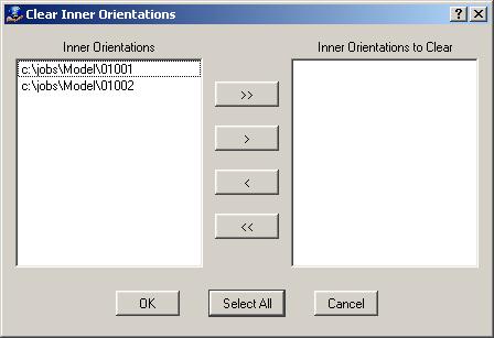
Clear Inner Orientations
Displays a dialog box to clear inner orientation on one or more images in the current project.
Clear Exterior Orientations
Displays a dialog box to clear exterior orientations on one or more images in the current project.

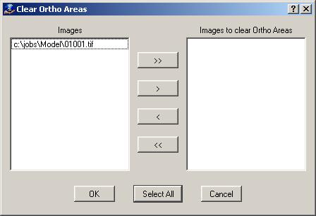
Clear ortho areas
Displays a dialog box to clear ortho areas on one or more images in the current project.
Create Menu
Create Orthos
Displays a dialog box to select multiple images for ortho generation.
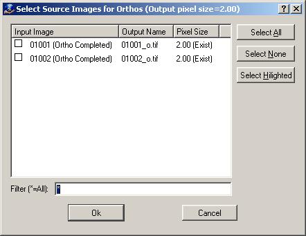
Displays the current output name for each image. Any images that do not already have an ortho image or that have an ortho image with a different pixel size than the current setting are selected automatically. Select the input images for which orthos should be generated then press "OK". A dialog box will display the output status.