Vr Mapping |
ON-LINE REFERENCE DOCUMENTATION CARDINAL SYSTEMS, LLC |
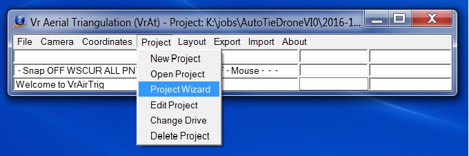
The Project Setup Wizard
Type: Utility within VR AT for project setup.
This utility walks users through setting up a project and verifying that input data is correct prior to starting AT. It is a windows wizard style interface and as such is largely self documenting. The instructions here are given for completeness and reference. Fore ease of use and consistency the style of the interface is very similar in VR AT, VR Model Set and VR Ortho/Mosaic.
The Wizard is accessed through the command ribbon (see image below) or by the command ProWiz.
Contents
Control Files
Importing Interior Orientations
Importing Exteriors Orientations
Double-click of Control Points Field
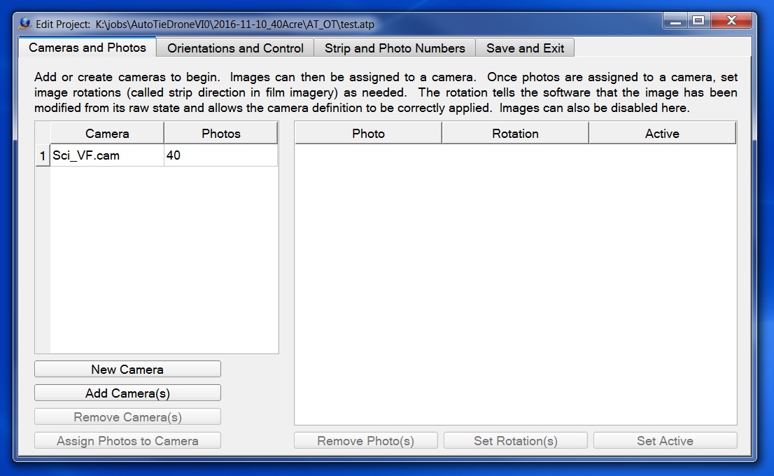
The first tab is for organizing your cameras and photos. Cameras must be defined first because images are required to be assigned to a specific camera. The 'New Camera' and 'Add Camera(s)' button accomplish this. Both use the camera edit utility. Once a camera is in the project double clicking on it's name will open in the camera edit utility.
To add images to project click on the name of camera the images will be assigned to in the left table. When a single camera is selected the 'Assign Photos to Camera' button on the bottom left becomes active. Click this button and navigate to choose the images. The names of images assigned to selected cameras are displayed in the right table. The number of photos assigned to each camera is listed next to the camera name in the left table.
Select groups of images to 'Remove Photo(s)', 'Set Rotations', and/or 'Set Active' using the buttons below the right table. If there are no images selected then these buttons will be disabled.
'Remove Photo(s)' removes them from the project but does not delete or otherwise modify the files.
Users are advised to avoid having to set rotations. It is only necessary to set rotations if the images have been saved rotated on the disk. If they have then VR needs to know so that principal point offsets and distortion parameters can be correctly applied. However, this is a road that usually leads to confusion. It much less confusing to rotate how images are displayed rather than save them rotated and try to get the rotations set correctly.
Setting and image inactive is functionally similar to removing it from the project, but may be easier for project management.
Tab 2: Orientations and Control
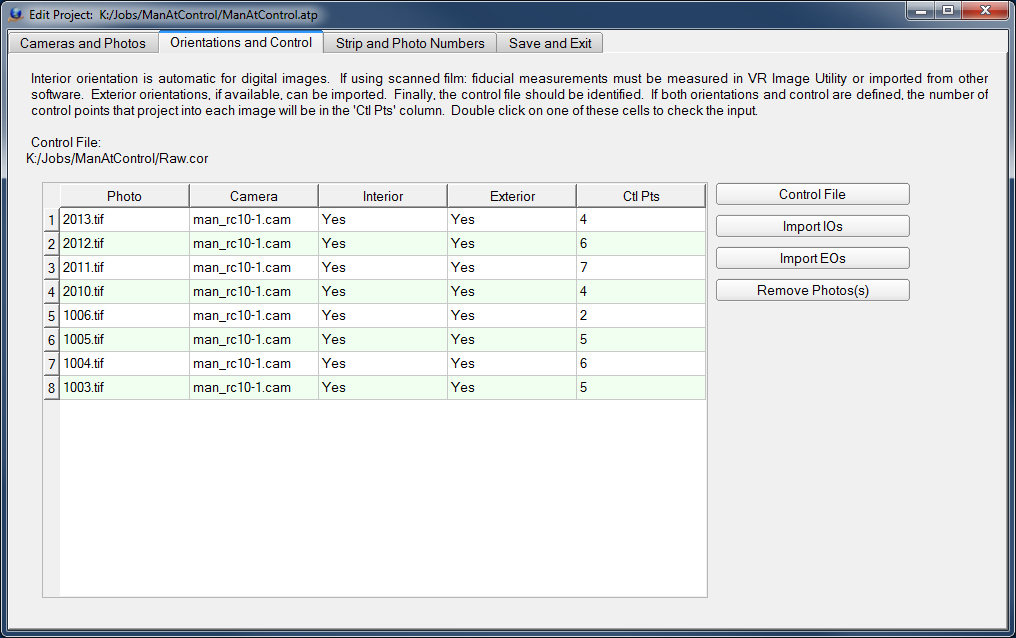
Control Files
On the 'Orientations and Control' tab of the project wizard the 'Control File' button is used to select ground control file. The control file can be file formatted as follows:
PtName1 X Y Z
PtName2 X Y Z
PtName3 X Y Z
...
VR adds some default header information when it saves the file.
File Example:
# Coordinate File
# Layout - Field Order Min number of fields
# 0 NAME X Y Z CX CY CZ 3
# 1 NAME Y X Z CY CX CZ 3
# 2 X Y Z NAME CX CY CZ 4
# 3 Y X Z NAME CY CX CZ 4
# 4 NAME X Y Z 3
# 5 NAME Y X Z 3
# 6 X Y Z NAME 4
# 7 Y X Z NAME 4
# 8 X Y NAME 3
# 9 Y X NAME 3
#
# Format - Coordinate format
# 0 State plane
# 1 UTM
# 2 Geographic Decimal Degrees
#
# SpZone - State plane zone
#
# Datum - Datum
# 0 NAD1927
# 1 NAD1983
#
# UtmZone - UTM Zone
# 1-60 Utm zone number
#
# Units - Coordinate units
# 0 Us Foot
# 1 International Foot
# 2 Meters
#
Layout 4
Format 0
SpZone 901
Datum 0
UtmZone 17
Units 0
#
5 1862600.861000 724626.555000 807.1600
14 1862956.537000 726104.024000 810.4900
27 1862097.709000 729995.080000 793.1600
29 1865529.981000 731805.394000 808.5700
30 1861813.412000 731226.056000 794.1000
103 1875804.906000 722601.108000 894.5390
104 1876434.487000 726668.853000 899.2450
107 1868807.915000 727037.911000 797.9120
110 1873497.612000 726632.340000 912.9600
227 1863885.554000 727376.236000 810.9500
528 1864669.954000 723806.413000 816.2600
Importing Interior Orientations
Interior orientations are automatic for digital images.
For scanned film images the interior orientations can be imported using the 'Import IO' button. See Import, Interior Orientations for more information.
Importing Exterior Orientations
Exterior Orientations can be imported using the 'Import EOs' button. Many formats are supported. See Import, Exterior Orientations for more information. At present only importing EO files is supported.
Double-click of Control Points Field
If the number of Control Points is greater than zero, the number of control points field may be double clicked to view photo thumbnails of a control point area. If the number of control points is greater than one a dialog will allow the selection of the control point to view.
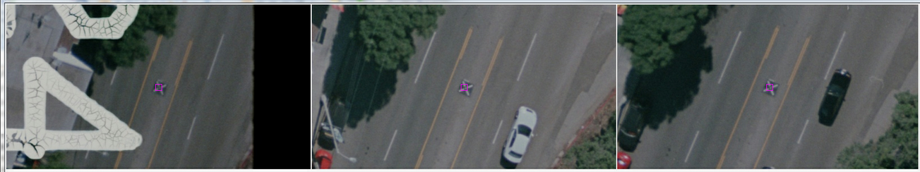
Photo thumbnails displaying the area around a control point
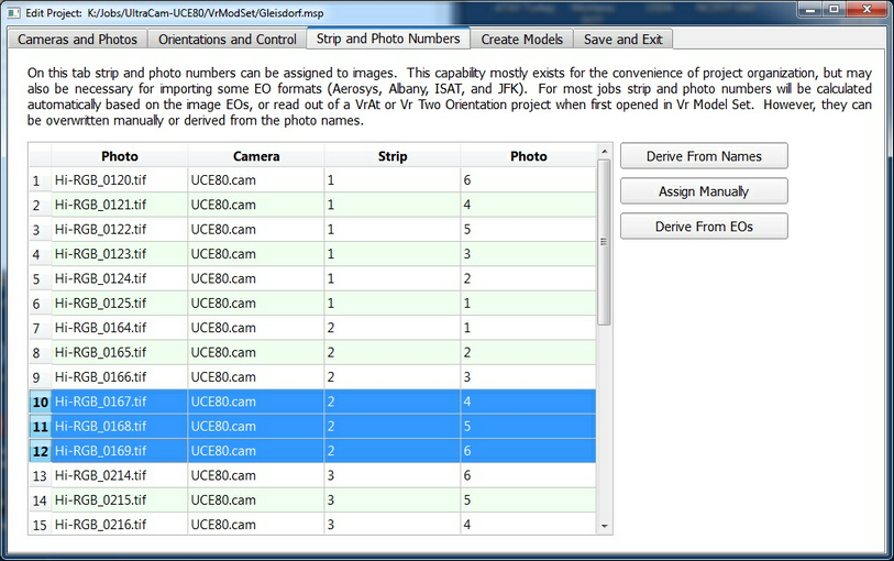
Tab 3: Strip and Photo Numbers
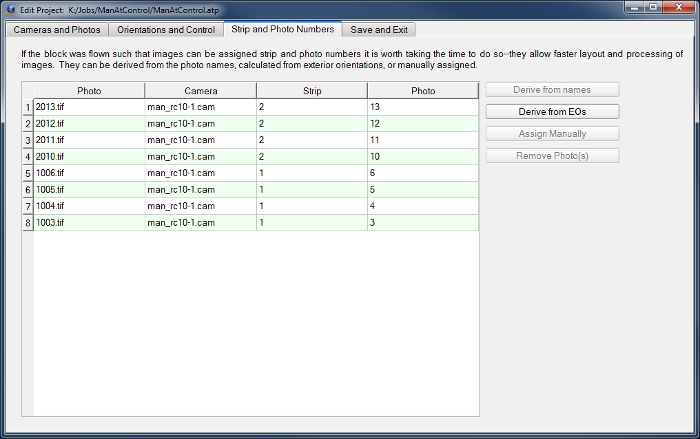
Strip and Photo Numbers
Photo strip and photo numbers make job organization and management easier. The Strip and Photo Numbers tab allows the assignment of strip and photo numbers to photos. Although this capability exists for the convenience of project organization, it may be needed for importing some exterior orientation formats such as Aerosys, Albany, ISAT and JFK. Strip and photo numbers allow models to be named in a meaningful way that communicates the individual model's relation to the whole project.
For most jobs strip and photo, numbers can be calculated automatically based on the image EOs. If there are no EOs or it is necessary to match the strip and photo numbers in and EO file the strip and photo numbers can be overwritten manually or derived from the photo names.
The Strip and Photo Numbers tab in the Edit Project dialog
Derive from Names
Obtains the strip and photo numbers based on the photo files names. A photo or group of photos may be highlighted and pressing the "Derive from Names" button will display the following dialog.
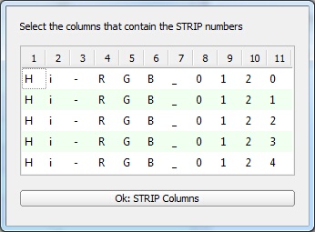
Select strip and photo number columns
In the above example the first five photo names are displayed (Hi-RGB_1020.tif). The columns that make up the strip number can be highlighted then the Ok button can be pressed. The columns that make up the photo number can then be highlighted and the Ok button can be pressed. For example, if columns 8 and 9 were selected and the strip number and columns 10 and 11 were selected as the photo number then photo Hi-RGB_1020.tif would be assigned a strip number of 10 and a photo number of 20.
Clicking on this tab saves the project and exits the wizard. Alt-s can be used to save the project at any time.