Vr Mapping |
ON-LINE REFERENCE DOCUMENTATION CARDINAL SYSTEMS, LLC |
VrTwo Orientation - Batch Import of ISAT Exterior Orientations
VrTwo Orientation Tutorial describing the importing of Exterior Orientations using the ISAT parameter file in batch mode.
VrTwo Orientation creates stereo image pairs or models for viewing in the VrTwo and VrLite. Stereo models may be generated manually or by importing the results from various aerial triangulation programs. Orientations may be performed on a single model, or multiple models may be oriented in a batch mode. The importing of models from aerial triangulation may be performed from the exterior orientations or from the measurements used to tie images and strips together. This tutorial will address importing orientations for multiple models using the ISAT exterior orientation file.
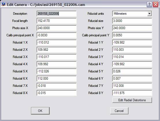
Creating or Editing the Camera File
New Camera (NewCam)
The New Camera function allows the user to create and edit a new camera calibration file. The user will be prompted for the file name for the new camera. Camera files in Vr Mapping have the .cam file name extension. See Edit Camera below for information on editing a camera file. Please note that this feature may not be required if a preexisting camera file is present.
Creating the Camera File
1. Click "Camera" then "New Camera" or "Edit Camera".
Please see Reference information for more information on the section.
Creating a Control File (NewCoo)
Create a new coordinate file if one does not exist. Click on "Coordinates" then "New Coordinate File".
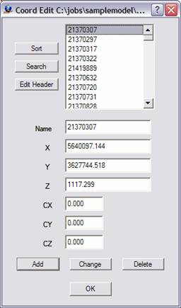
If a control file exists and contains the PointName X Y Z fields, it can be used directly by Vr Mapping programs. Simply rename the file by replacing the file postfix with .cor. For example, if a coordinate file named TheCoords.txt contained the PointName X Y Z fields, then it could be renamed TheCoords.cor and be used by VrTwo Orientation.
The following is an example of contents of a coordinate file compatible with Vr Mapping:
201 837831.194130 951352.037020 303.8200
202 836399.079330 951266.642540 337.6800
203 837994.618340 950634.951710 299.6000
204 836711.670600 950565.198920 326.3200
205 836018.411470 950724.804370 309.2900
The coordinate file comprises the point name followed by the X, Y and Z coordinates.
Creating or Editing the Project
The following steps are required to create the project:
| 1. | Create a New Project File - Click on "Project", then "New Project" or "Edit Project". |
| 2. | Add Coordinate File - Click the button to the right of the “Coordinates” box to add the Coordinate file. |
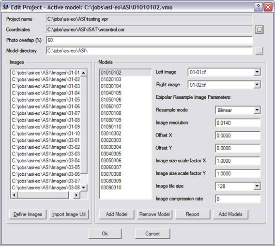
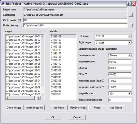
A example of the Edit Project dialog box.
3. Define Images - Click the "Define Images" button in the edit project dialog box. The "Edit Project - Define Images" dialog box allows definition of multiple image files. Each image file has a Photo Name Format, which are parameters that define the strip and photo number from an image file name. Strip direction, pixel size and the "Open In Layout" flag are also defined for each image. The top portion of the dialog box is a template of these parameters that may be copied to an image or group of images by selecting an image or dragging the cursor over a group of image rows then pressing the Apply button for that item.
4. Click on the "OK" button to return to the main project setup dialog box.
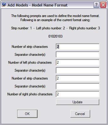
5. Create Model Names - Click the "add models" button to create models. Pressing this button allows the batch creation of the VrTwo Orientation model files. Model name format is used to set the parameters that define the strip and photo number from an image file name.
For more information, please see VrTwo Orientation - Photo Name Format.
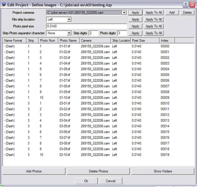
A Example of the define images dialog box.
The following are descriptions of the parameters in the Edit Project - Define Images dialog box:
Project Camera
The Project cameras (.cam) files are assigned to individual images. Up to 10 camera files may be defined.
Film Strip Location
The film strip location defines the direction flight. For more information, please see VrTwo Orientation - Film Strip Direction.
Photo Pixel Size
The photo pixel size is in the same fiducial units (millimeters, inches, or pixels) as the Camera file. If this value is unknown, it can be computed after reading three points in Inner Orientation at the bottom left of the Interior Orientation window.
Add Photos
Adds images to the project.
Photo Name Format
Sets parameters that define the strip and photo numbers from an image file name. For more information, please see VrTwo Orientation - Photo Name Format.
6. Press "OK" when complete.
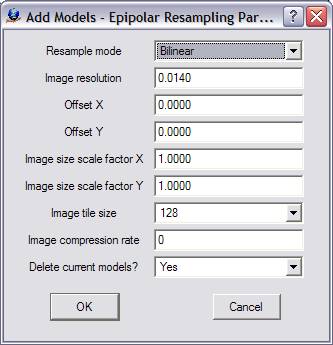
7. Epipolar Resampling Parameters - Enter the epipolar resampling parameters for the batch configuration of all models. See VrTwo Orientation for more information on epipolar resampling methods.
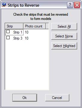
8. Select Strip Reversal - If a strip is checked, its measurements are rotated 180 degrees from their original orientation. This may be required for a strip whose Strip Location is to the right.
9. Click "OK" to start the model generation process.
Section 2 Importing Orientations
Importing Interior Orientations in Batch Mode
| 1. | Click Import -> Import Interior Orientations Batch from the VrTwo Orientation main window. |
| 2. | Select the ISAT photo file name and Interior Orientation file format. |
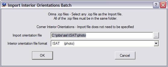
Import Orientation File
Defines the ISAT parameter file name that contains the orientation parameters. This file is normally named "photo".
Interior Orientation File Format
Defines the input format. Should be "ISAT (photo)".
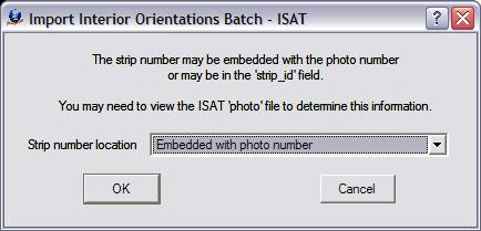
| 3. | Select the strip number location, which defines the location of the strip number in the "photo" file. Review the ISAT photo file to see how the strip number is encoded. It may be encoded within the photo name after the "photo_measurements" keyword. Alternately, it may follow the "strip_id" keyword. In the example below, the strip number is part of the photo name. For more information, see ISAT Photo File Format. |
begin photo_measurements 01-02 strip_id 01 version 2.0
21370307 -12.313744 -61.250663 -12.312909 -61.246508 1 85
21370297 -3.3020941 -68.078501 -3.3018724 -68.073928 1 85
21370317 -5.2376813 -75.449179 -5.2373545 -75.44447 1 85
21370322 -14.481854 -68.898072 -14.480887 -68.89347 1 85
21370344 -0.68857854 -82.631939 -0.68853523 -82.626727 1 85
Defining the location of the strip number in the "photo" file
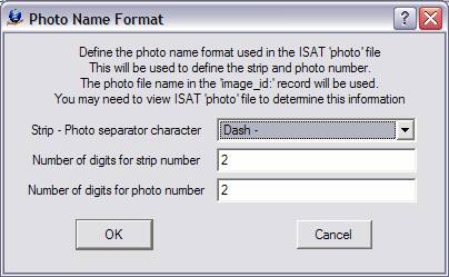
4. Set Strip Photo Separator - This defines the file format of the image names and how the strip and photo number are parsed by VrTwo Orientation. The Photo Name Format dialog will be displayed if the strip number location is set to "Embedded with photo number" in the previous prompt. For more information see Photo Name Format.
5. Press "OK" to advance to the next step.
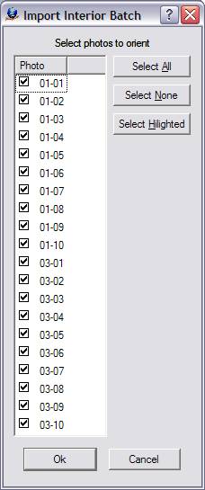
6. Select Photos To Import - Sets the photos to be used in the Interior orientation.
7. Select Strip Reversal - If a strip is checked, its measurements are rotated 180 degrees from their original orientation. This may be necessary for any strip whose Strip Location is to the right.
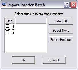
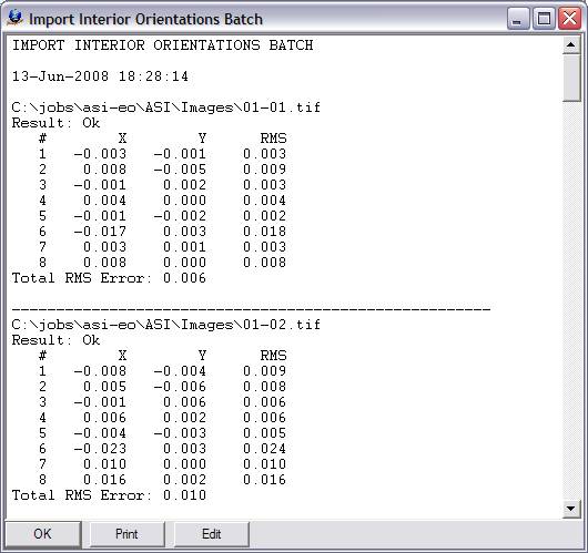
8. Start the Import by clicking "OK". Results and residuals will be presented as shown below.
Importing Exterior Orientations Batch
| 1. | Click Import -> Exterior Orientation Batch. |
| 2. | Select Exterior Orientation File Format -> ISAT photo file, or ISAT EO file (.txt). |
| 3. | Select the Exterior orientation file or ISAT photo file . |
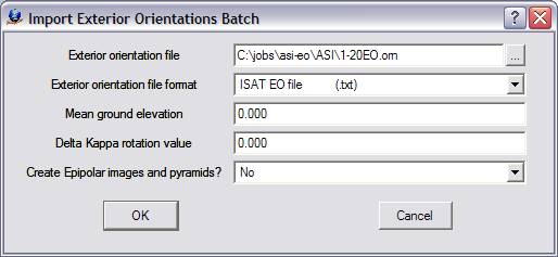
Mean Model Ground Elevation
Defines the average ground elevation of the model or job. This value may be approximate.
Delta Kappa Rotation Value
Some situations require a rotation angle to be added to the Kappa (rotation about the Z axis) value in the exterior orientation file. This action is required if the images were rotated from their original positions. It is suggested that an angle of zero is first attempted. If the import does not produce a viewable stereo model, an import with a rotation value of 180 should be performed. The possible rotation values are 0, 90, 180 and 270 degrees.
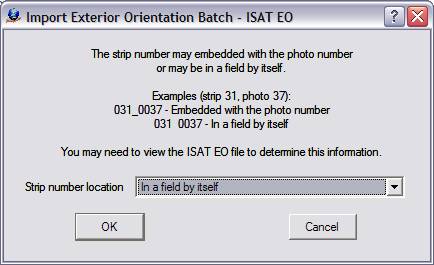
4. Select Strip Number Location - Specifies whether the strip number is embedded within the photo name. Review the ISAT EO file to see if the strip number is embedded within the photo number.
1 01 863230.000000 386737.000000 4228.000000 0.000000 0.000000 205.142223
1 02 863240.735165 386879.525737 4209.111350 0.202415 -0.935304 -151.577746
1 03 862429.391346 386476.275096 4221.006168 -0.398444 -0.795670 -151.209903
1 04 861603.826122 386093.443243 4225.211811 -1.267587 -1.013214 -151.091062
1 05 860778.552256 385723.782038 4211.906057 -0.938446 -1.254254 -151.900580
5. Set Strip Photo Separator - Defines the file format of the image names and specifies how the strip and photo number are parsed by VrTwo Orientation.
For more information, please see Photo Name Format.
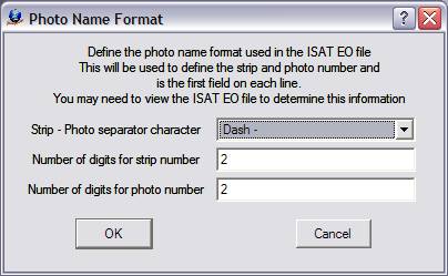
The Photo Name Format definition dialog box
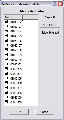
6. Select models to orient then press "OK" to start the import process.
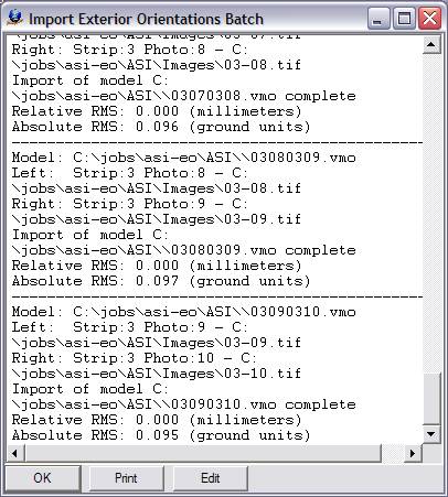
| 7. | Review import results and total RMS values for Absolute and Relative orientations. The total RMS values should be reviewed to verify that the import was successful. When finished, click "OK" to continue. |
| 8. | Click on Import -> Create epipolar images batch. |
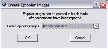
9. Click "OK". The process can be lengthy, so feel free to take a break while the epipolar images are being built.
| 10. | Click "OK" again when the epipolar batch process is finished. |
Section 3 Opening Models in VrTwo
1. Start VrTwo.
2. Click on File -> Open Model or use the Open Model (OpeMod) command. Navigate to the location of the project folder by double clicking the far left hand box.
3. Double click on the VrTwo Model (.vmo) file and press "OK".
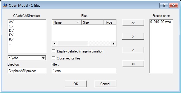
The Open Model dialog box
4. VrTwo will now generate pyramids for the epipolar images if they do not already exist.
5. Open a VrOne File by clicking on File -> Open Vr File or by using the Open VrOne File (OpeVr) command. Navigate to the project folder by double clicking the far left hand box.
6. Double click the VrOne (.vr) file.
The stereo model should open and the stereo model and vectors should be seen on the screen. If the stereo window does not show a stereo image and vectors, try using the Drive Control (Cd) command. Typing "Cd 1" will drive to the first control point in the model. For more information, please see the Getting started with VrOne/VrTwo tutorial, which covers basics of data collection and editing.
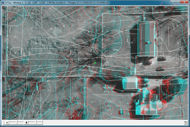
The VrTwo graphics window showing the stereo model (Anaglyph)