Vr Mapping |
ON-LINE REFERENCE DOCUMENTATION CARDINAL SYSTEMS, LLC |
VrTwo Orientation - Single Model
Section 2 Interior Orientation
Section 3 Relative Orientation
Section 4 Absolute Orientation
Section 5 Opening Model in VrTwo
VrTwo Orientation creates stereo image pairs (or models) for viewing in VrTwo and VrLite. Stereo models may be generated manually or by importing the results from various aerial triangulation programs. Orientations may be performed on a single model or multiple models in a batch mode. Models may be imported from aerial triangulation using exterior orientations or the measurements used to tie images and strips together.
Cardinal Systems provides a sample data set for use with this tutorial on single model orientation. Please see Sample Data Set to download the sample data. Contact Cardinal Systems for the username and password for the download.
Requirements to Complete a Single Model Orientation
| 1. | Camera File - The camera file may either be imported or generated from a camera calibration report. |
| 2. | Ground Control File - The ground control file contains points obtained from sources like ground surveys. |
| 3. | Images - Images are raw, unedited, unmodified image files. |
| 4. | Correct Image Overlap - The image overlap must be on inside of images or in ortho mode. Images may need to be rotated to fulfill this criterion. Image rotation should be done before Interior Orientations are performed. If image rotation is required, this task can be performed in batch using the Vr Image Utility program. |
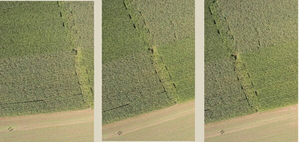
An example of photo overlap to the inside (ortho)
Creating or Editing the Camera File
New Camera (NewCam)
Allows the user to create and edit a new camera calibration file. Prompts user for the new camera's file name. Camera files in Vr Mapping have the .cam file name extension. See Edit Camera below for information on editing a camera file. If a preexisting camera file exists, this feature may not be needed.
Creating the Camera File
From the "Camera" dropdown menu, click on either "New Camera" or "Edit Camera".
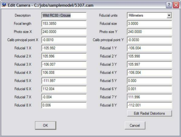
The Edit Camera dialog box
Creating or Editing a Control File
If one does not already exist, create a new coordinate file. From the "Coordinates" dropdown menu, click on "New Coordinate File". Please see VrTwo Orientation New Coordinate File for more information.
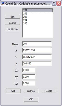
The Edit Control dialog box
If a control file exists and contains the PointName X Y Z fields, it can be used directly by Vr Mapping programs. Simply rename the file by replacing the file postfix with .cor. For example, if there were a coordinate file named TheCoords.txt which contained the PointName XYZ fields, it could be renamed TheCoords.cor and be used by VrTwo Orientation.
The following is an example of a contents of a coordinate file compatible with Vr Mapping:
201 837831.194130 951352.037020 303.8200
202 836399.079330 951266.642540 337.6800
203 837994.618340 950634.951710 299.6000
204 836711.670600 950565.198920 326.3200
205 836018.411470 950724.804370 309.2900
The first field is the point name. The following fields are the X, Y and Z coordinates.
Creating or Editing the Project
The following steps create the project:
| 1. | Create a New Project File - From the "Project" dropdown window, click on either "New Project" or "Edit Project". |
| 2. | Add Coordinate File - Click the button to the right of the “Coordinates” box to add the coordinate file name. |
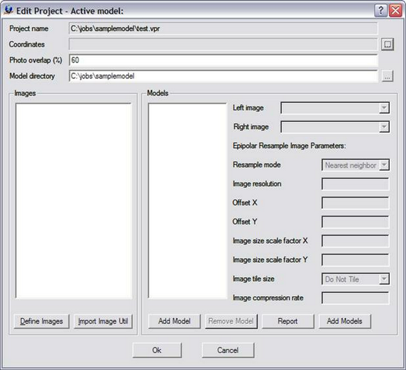
The Edit Project dialog box prior with no parameters defined
3. Define Images - Click the "Define Images" button in the "Edit Project" dialog box. The "Edit Project - Define Images" dialog box allows the definition of multiple image files. Each image file has a Photo Name Format, which are parameters that define the strip and photo number from an image file name. Strip direction, pixel size and the "Open in Layout" flag may also be defined for each image. The top portion of the dialog box is a template of these parameters. This template may be copied to an image or a group of images by selecting the desired file(s) then pressing the "Apply" button.
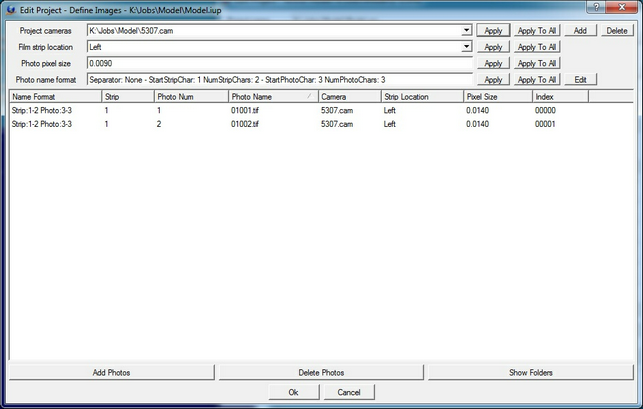
The Edit Project - Define Images dialog box
The following are descriptions of the parameters in the "Edit Project - Define Images" dialog box:
Project Camera
Project cameras (.cam) are assigned to individual images. Up to 10 camera files may be defined.
Film Strip Location
Defines the direction flight. For more information please see VrTwo Orientation - Film Strip Direction.
Photo Pixel Size
The photo pixel size is in the same fiducial units (millimeters, inches, or pixels) defined by the Camera file. If this value is unknown, it can be computed after reading three points in Inner Orientation at the bottom left of the Interior Orientation window.
Add Photos
Adds images to the project.
Photo Name Format
Sets the parameters that define the strip and photo number from an image file name. For more Information please see VrTwo Orientation - Photo Name Format.
4. Create Model Names
Click "Add Model" to create a new model. Pressing this button allows a single model to be added to the list of models. After the model is added, the left and right images must be selected and the epipolar re-sampling image parameters must be set.
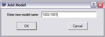
The Add Model dialog box
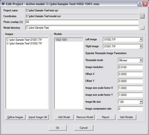
The Edit Project dialog box showing Model 1002-1001
Please see VrTwo Orientation - Project for more information.
Section 2 Interior Orientation
Interior Orientation determines the interior perspective of an image by assigning a coordinate system and applying the camera calibration. This is normally done with a least-squares adjustment between known and measured fiducial point coordinates. When using film, the interior orientation compensates for film shrinkage or expansion. Camera calibration information is required by Interior Orientation. There are four methods of performing interior orientations in the VrTwo Orientation program.
| • | Automatic - Auto-correlated automatic interior orientation processing is available in the Vr Image Utility - Automatic Interior Orientation (imageutill.exe) program for metric cameras with fiducial marks. |
| • | Importing Orientations - Interior orientations can be imported from several Aerial Triangulation packages. |
| • | Corner Interior Orientations - This method uses the the four corners of the images to create an Interior Orientation. This method is for non-metric cameras without fiducial marks. |
| • | Manual - Fiducials may be measured manually. This is the method that will be used in this tutorial.. |
To begin the Left Interior Orientation process, select "Left Interior Orientation" from the "Orientation" dropdown menu. Note that checkmarks appear next to each orientation step after it is performed. When the orientation process is fully completed, each step will have a checkmark next to it.
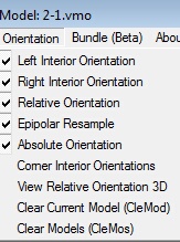
The Orientation pull-down showing a completed orientation
Measuring Fiducials
5. Measure the fiducials that were entered into the VrTwo Orientation camera file.
On a standard camera (with eight fiducials), it is recommended that all eight be measured. Measuring fiducials requires some or all of the following steps:
| • | Center the floating mark over a fiducial then right mouse click to center the image. |
| • | Press the page down button on the keyboard to zoom in. |
| • | Left mouse click to measure a fiducial. If "Advance after measurement" is checked, VrTwo will zoom to the next fiducial. Once three fiducials are measured, VrTwo Orientation will drive to where it believes the next point is based on the settings in the camera file. |
These functions can be seen in the "Interior Orientation Menu Keys" dialog box. Use mouse buttons instead of the box to more effectively measure and view fiducials.
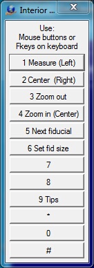
Interior Orientation Menu Keys
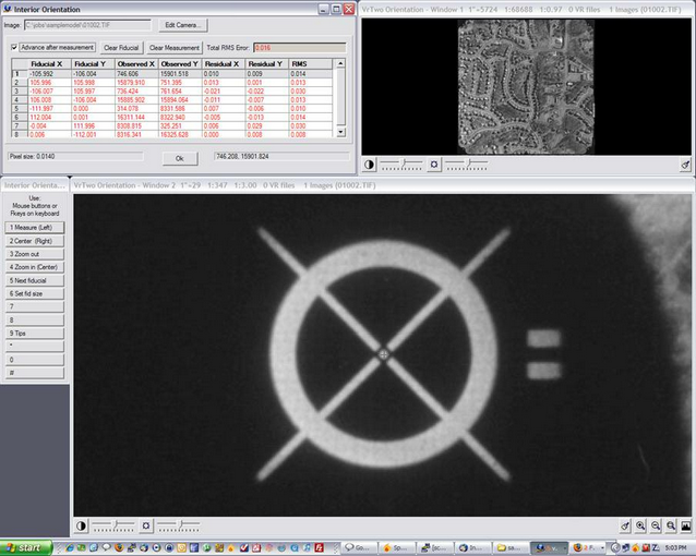
The manual Interior Orientation environment
6. Continue this process until all fiducials have been measured. The "Interior Orientation" dialog box will display the residual for each point and the total RMS error.
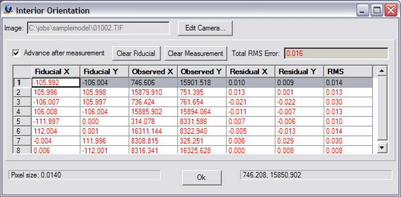
The Interior Orientation dialog box showing point residuals and the total RMS error
7. To begin the right interior orientation process, select "Right Interior Orientation" from the "Orientation" dropdown menu. Repeat steps 5 and 6 (as shown above) for the right image.
For more information please see VrTwo Orientation - Interior Orientation.
Section 3 Relative Orientation
Relative Orientation aligns the two images of a stereo pair so they can be viewed in 3D. This is done by observing common points on each image and, in effect, tying the images together. Another least-squares adjustment is performed on these observed points. Relative orientation requires an Interior Orientation. Three methods exist to measure points. All three methods are available for each point. Because ground features change from point to point (one point may be on a city street and the next in trees), one method of measurement will not suit all situations. The measurement methods are:
| • | Mono-comparator - A common point is selected in the left image. The same point is selected on the right image. "Measure" (left mouse or button 1) is used to measure the point on the left and right images. |
| • | Semi-automatic correlation assist - The cursor is positioned on one photo and its corresponding location is found on the other photo by pressing the "Correlate" button (system keyboard F7 or button 7). When using correlation assist, the cursor is positioned (without any button presses) in one of the measurement windows. "Correlate" is then engaged to find the corresponding point in the other photo. The matching point is displayed in the other measurement window. The cursor may be placed in the left or right measurement window. After correlation, the results are displayed in the At Measure dialog box and in the Menu Keys dialog box. A result of 0.9 to 1.0 is good; 0.8 to 0.9 acceptable: 0.7 to 0.8 poor; less than 0.7 should lead to rejection of the correlation. |
| • | Stereo - The two images are displayed in stereo and parallax is cleared at the point location. This operation is similar to the method used on analytical stereo-plotters. Options in this mode include image correlation, dove prism adjustment (rotation of one photo), and photo scale factor adjustment (changing the scale of one photo). |
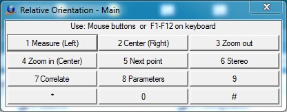
The Relative Orientation Menu Keys dialog box
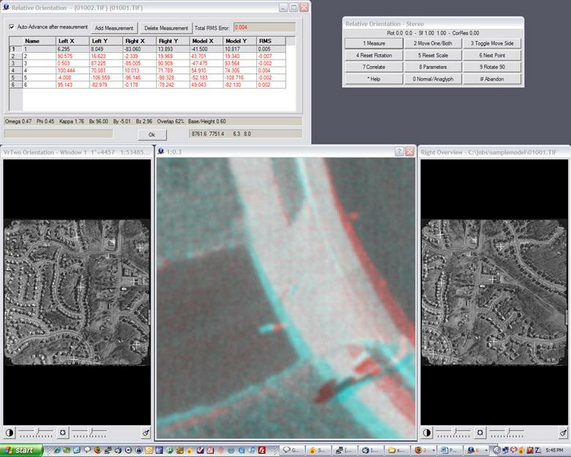
Measuring a point in Relative Orientation using the stereo method (Anaglyph)
Please see VrTwo Orientation - Relative Orientation for more information.
When all the points in Relative Orientation have been measured and are acceptable, the OK button may be pressed. Epipolar images may now be created from the results of Relative Orientation. Epipolar images are stereo viewable images with a common scale. They have their image rotations removed and make stereo viewing comfortable for the operator.
If epipolar images are not desired at this point, this step may be skipped and epipolar images may be created later from the Orientation menu.
Please see VrTwo Orientation - Epipolar Images for more information.
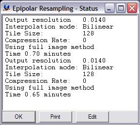
The information window displayed during epipolar image generation
Section 4 Absolute Orientation
Absolute Orientation defines the transformations between the model space achieved through relative orientation and a known ground or object space coordinate system. Again, a least-squares adjustment is performed to obtain these transformations. An exterior orientation is created for each image. A relative orientation solution and control point file in the project coordinate system is required to perform an Absolute Orientation.
There are two stereo viewing modes available in Absolute Orientation: static and roaming. In static mode, the images remain stationary and the cursor moves. In roaming mode, the images move and the cursor stays in the middle of the stereo window.
To set the stereo viewing mode to roaming, click File -> Preferences and set "Use roaming mode in Absolute?" to "Yes".
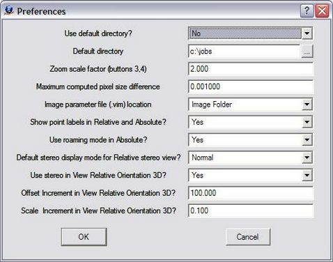
VrTwo Orientation preferences dialog box
Measuring Absolute Orientation Points
In the Absolute Orientation process, known ground control points are measured.
1. Click Orientation -> Absolute Orientation from the main window.
2. Locate the first on the image (please see control diagram below).
3. Use the wheel on the mouse to adjust the Z value of the floating mark to the ground or target. Note that holding the Shift key or Control key while moving the wheel will increase the speed of the Z movement.
4. Center the cursor over the point location and press the left mouse button. This will measure the point. If "Auto-Advance after measurement" is checked, VrTwo will drive to the next point in the control file.
5. Move to the next point and repeat the measurement process. Continue the measurement process until all of the control points that fall within the model have been measured.
6. Once enough control points have been measured, point and overall residuals will be displayed in the "Absolute Orientation" dialog box. Pressing "Ok" in this dialog box saves the orientation and exits Absolute Orientation.
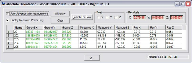
Measured control points with residuals in the Absolute Orientation dialog box
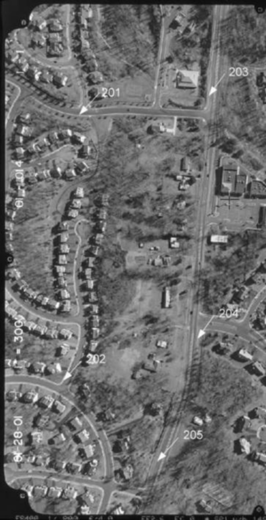
Control points diagram overview
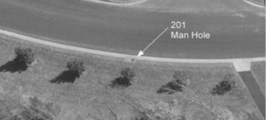
Location of ground control point 201
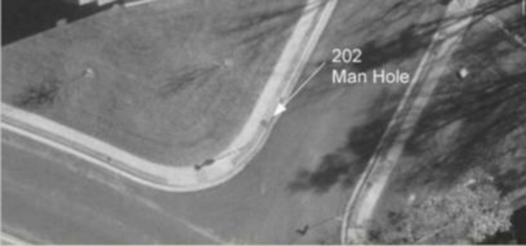
Location of ground control point 202
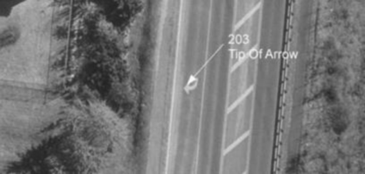
Location of ground control point 203
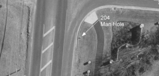
Location of ground control point 204
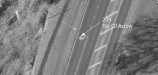
Location of ground control point 205
For more information please see VrTwo Orientation - Absolute Orientation.
Section 5 Opening the Model in VrTwo
1.Start VrTwo.
2.Click on File -> Open Model or use the Open Model (OpeMod) command. Navigate to the location of the project folder by double clicking the far left hand box.
3.Double click the VrTwo Model File (yourfilename.vmo) and press "OK".
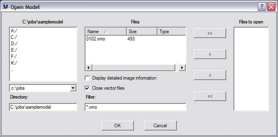
The VrTwo Open Model dialog box
4. VrTwo will generate pyramids for the epipolar images if they do not already exist.
5.Open a VrOne File by clicking on File -> Open Vr File or using the Open VrOne File (OpeVr) command. Navigate to the project folder by double clicking the far left hand box.
6. Double click on the model.vr file supplied with the sample data.
The stereo model should open and the stereo model and vectors should be seen on the screen. If the stereo window does not show a stereo image and vectors try using the Drive Control (Cd) command. Typing "Cd 1" will drive to the first control point in the model. For more information, please see the Getting started with VrOne/VrTwo tutorial, which covers the basics of data collection and editing.
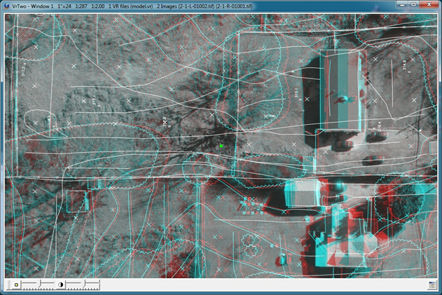
The VrTwo graphics window showing the stereo model (Anaglyph)
VrTwo Orientation Video
To view the video demonstrating the orientation process described above see VrTwo Orientation .