Vr Mapping |
ON-LINE REFERENCE DOCUMENTATION CARDINAL SYSTEMS, LLC |
VrMosaic Tutorial
This tutorial will walk you through all of the steps needed to create mosaic images using VrMosaic. This is not intended to demonstrate all of the features in VrMosaic, but will serve as a general guide to the mosaicing process. Please see the VrMosaic Documentation for detailed information on all VrMosaic features.
Setting Project Parameters (Video)
Preparing to Collect Seams (Video)
Collecting Strip to Strip Seam Lines (Video)
Collecting Image to Image Seam Lines (Video)
Collecting Using Closed Seams (Polygon Mode)
In this section of the tutorial, you will launch VrMosaic and start the Mosaic application. It is assumed that the VrMosaic program has already been installed on the computer.
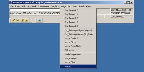
| 1. | Select the Start->Programs->VrOne->Vr Mosaic menu item to launch the Vr Mosaic program. The VrMosaic main window should be displayed along with one graphics window. |
| 2. | Select "Mosaic" from the "Image" dropdown menu. Alternately, the command MOS can be entered to the command prompt area or the mosaic icon can be clicked. This displays the Mosaic application dialogs and two additional graphics windows. |
In this section of the tutorial, the Project Parameters dialog box will be used to define new project settings.
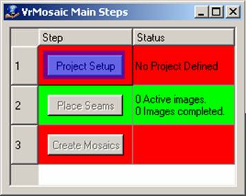
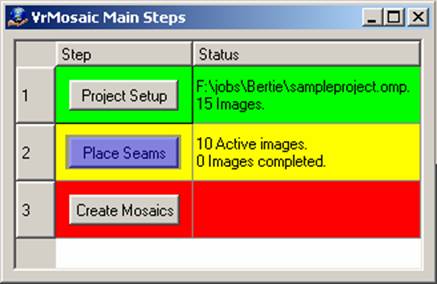
| 1. | Select the “Project Setup” button in the VrMosaic Main Steps dialog or select “7. Enter Params” from the MenuKeys dialog. The project settings dialog box should be displayed. This dialog is separated into several tabbed pages that represent different areas of the project settings. Few items need to be changed in order to complete this tutorial. It is recommended that you become familiar with all project settings before completing the first mosaic project |
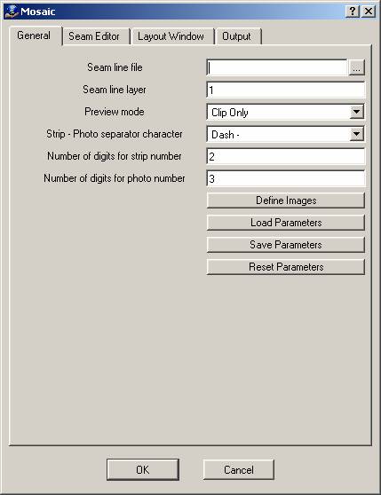
| 2. | Select the "General" tab. |
| 3. | Set the "Seam line file" parameter to the following: x:\the_job_location\seams.vr. |
NOTE: Replace x:\the_job_location\ with the location of an existing folder. Use the browse button (…) to select the location without having to type it in.
4. Set the "Strip-Photo separator character" to match the filename format of the ortho images.
5. Set the "Number of digits for strip number" and "Number of digits for photo number" to match the filename format of the ortho images.
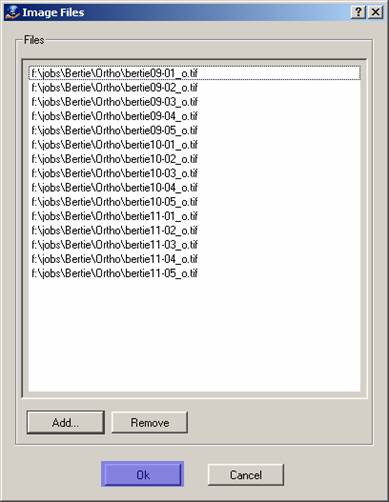
6. Select the “Define Images” button. This will display the "Image Files' dialog, which allows ortho images to be added and removed from the project.
7. Select the “Add…” button and use "Add Image Files" to add all of the ortho images to the project.
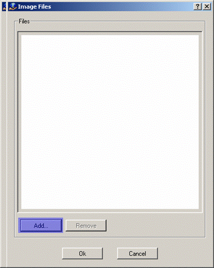
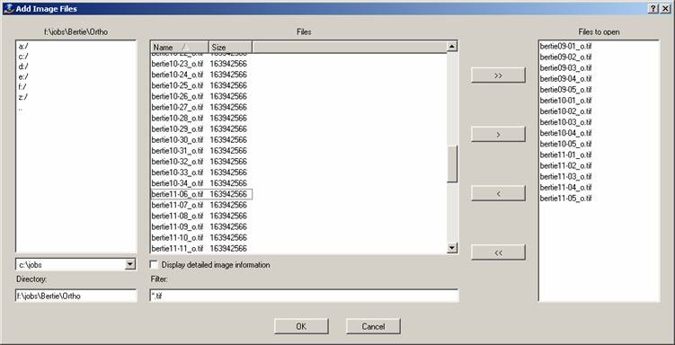
8. Select “OK” to close the "Add Image Files" dialog.
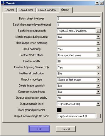
9. Select the "Output" tab.
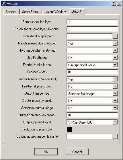
10. Set the "Batch sheet output path to: x:\the_mosaic_output_location\
NOTE: Replace x:\the_mosaic_output_location with the location of an existing folder. Use the browse button (…) to select the location without having to type it in.
11. Set the Output mosaic image file name to: x:\the_job_location\mosaic1.tif.
NOTE: Replace x:\the_job_location\ with the location of an existing folder. Use the browse button (…) to select the location without having to type it in.
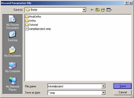
12. Select “OK”. You will be prompted to save the project settings to a file.
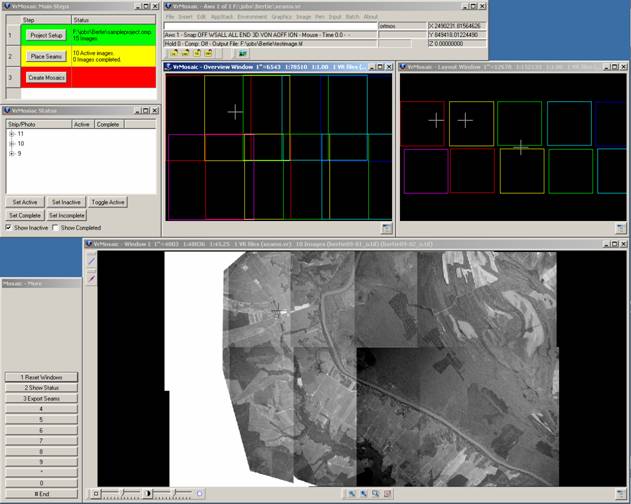
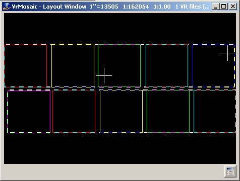
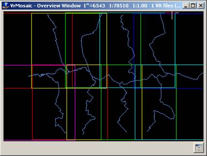
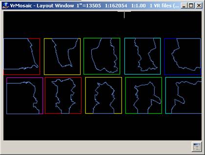
14. Type in a new filename for this project parameter file and click "Save". All of the images that were added to the project will now be opened. This may take a while if a large number of images were added and the images do not have pyramid files created yet. After the images have been opened, the results are displayed in all three graphics windows. By default the main graphics window (Window 1) will display images only in their true geographic location. The Overview window will show images and image borders in their true geographic location. The Layout window will show the image borders only in a default layout location with no images overlapping each other.
In this section of the tutorial, you will set up the project windows and activate a subset of the project images in preparation for collecting seam lines.
First, the windows should be arranged to make maximum use of the screen area.
1. Select “9. More options” from the MenuKeys dialog. This will display a new MenuKeys dialog.
2. Select “1. Reset Windows” from the MenuKeys dialog. This will display a confirmation dialog.
3. Select “Yes” in response to the Reset Window confirmation dialog.
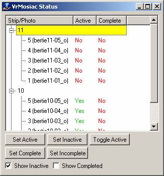
The next step is to deactivate all images that aren’t needed when collecting the current seam line. On large projects, having all images open and active can cause the seam line collection process to very slow. In most cases, necessary images comprise the current image strip and the strips above and below it.
1. Highlight all image strips in the VrMosaic Status dialog. This can be done quickly be pointing to a single image strip and pressing Ctrl-A.
2. Select the “Set Inactive” button. All of the images in the project should close. The graphics windows should now be empty.
3. Highlight the first image strip in the project along with any adjacent image strip. If starting with an image strip at the edge of the project boundary, only one other image strip will need to be highlighted. Hold down the Ctrl key while selecting image strips to allow multiple individual strips to be selected.
4. Select the “Set Active” button. This will open the images in the selected image strips. The graphics windows should now be displaying the images in the selected image strips.
In this section of the tutorial, seam lines will be collected using all collection methods.
Open seam lines are the primary method used to define seams in VrMosaic. Open seam lines are used to define a common seam between two overlapping images or two overlapping image strips. Open seam lines can be as simple as a two-point line, or can be very detailed containing thousands of points. The normal collection process consists of placing open seam lines between image strips, and then placing open seam lines between each image in the image strips.
Collecting Strip to Strip Seam Lines
In this section of the tutorial, you will collect two seam lines between two sets of image strips.
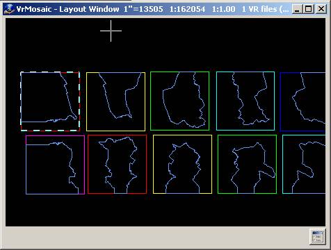
1. Select “Place Seams” on the VrMosaic Main Steps dialog or select “1 Place Seams” from the MenuKeys dialog. This will display a new MenuKeys dialog and the VrMosaic Place Seams Steps dialog. The layout window will highlight the active strips or images.
2. Make sure the status for step 1 (Toggle Seam Mode) in the VrMosaic Place Seams dialog is “Between Strips”. If not, press the “Toggle Seam Mode” button, or select “3 Tog Seam Mode” from the MenuKeys dialog.
3. Image borders will be displayed for all active images in the Layout window. If not, type “ZOOA” in the command prompt area then select anywhere in the Layout window.
4. The first two strips should be surrounded with a dashed highlight line in the Layout window. If not, point to and select the first image strip using button 1 in the layout window. The first image strip should now be highlighted along with the next strip. If the next strip is not highlighted, point to and select the second image strip using button 2.
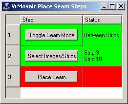
5. Make sure the status for step 2 (Select Images/Strips) in the VrMosaic Place Seams dialog displays the two strip numbers that you intend to place a seam line between. If not, follow the instructions in the previous step.
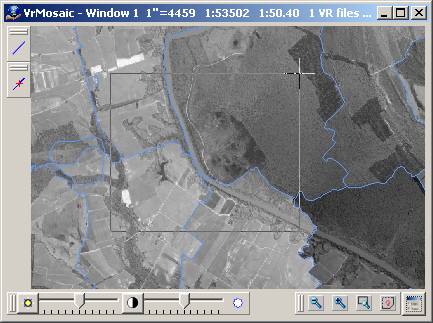
6. In graphics window 1, zoom close to one end of the image strips, and near the middle of the overlap area between the strips. This is can be done using the Zoom Window (ZOOWIN) command or by using the Home and Page Down keys to center and zoom in to the area.
NOTE: If using ZOOWIN, you will need to end the ZOOWIN command before continuing to the next step.
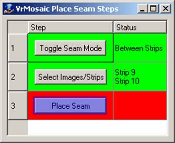
7. Select the “Place Seam” button on the VrMosaic Main Steps dialog or select “4 Place Seam” from the MenuKeys dialog. This will display a new MenuKeys dialog that provides options for collecting the seam line.
8.In graphics Window 1, position the cursor where you want the seam line to begin and press button 1 to digitize a point. A rubber-band line should be displayed from the point selected to the current cursor location.
9. Continue to use button 1 to digitize points along the seam line. Use the Zoom commands to zoom in and out as needed. You will notice that as each new point is added to the seam line, the image display changes to reflect how the images will be merged along the seam line. Use option “3 Backup” if you place a point in the wrong location.
10. If digitizing a large line, and there are many images in the project, the image update process may take a few second each time a new point is digitized. If this is the case, use “9 Tog Update”, to toggle the instant update feature off and on. Using this method several points can be digitized with update off, then turn update back on to see the results.
11. The Mosaic application will normally determine the direction (horizontal or vertical), and the image sides (left, right, top, or bottom) for the seam line. In some cases, the default settings may need to be changed. This can be done using options 6-8 on the MenuKeys dialog. Each seam line has one direction associated with it, either horizontal or vertical. Each seam has two sides associated with it, one for each image or strip that it divides. Seam line direction and side may need to be changed manually, for example, if seam lines occur along the edge of the project where there is no adjoining image or strip.
12. After all points have been digitized, select “4 End” from the MenuKeys dialog to end and save the seam line. The previous MenuKeys dialog will be displayed and the next two strips will be highlighted.
13. Repeat this process starting with step 5 until at least two strip-to-strip seam lines have been placed. The goal is to have one strip of images with a seam line on both sides of the strip.
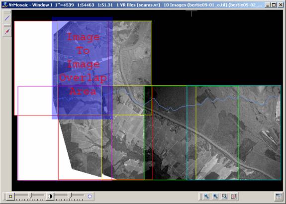
Collecting Image to Image Seam Lines
In this section of the tutorial, you will collect seam lines between all of the images in a strip.
1. Make sure the "Open Seams" MenuKeys dialog is displayed. If not, select “Place Seams” on the VrMosaic Main Steps dialog or select “1 Place Seams” from the MenuKeys dialog. This will display a new MenuKeys dialog and the VrMosaic Place Seams Steps dialog. The layout window will highlight the active strips or images.
2. Make sure the status for step 1 (Toggle Seam Mode) in the VrMosaic Place Seams dialog is “Between Images”. If not, press “Toggle Seam Mode” or select “3 Tog Seam Mode” from the MenuKeys dialog.
3. Image borders for all active images will be displayed in the Layout window. If not, type “ZOOA” in the command prompt area and then select anywhere in the Layout window.
4. Two images should be surrounded with a dashed highlight line in the Layout window. If not, point to and select the first image in the image strip. The image strip should already have a seam line on both sides. The first image should now be highlighted along with the next image. If the next image is not highlighted, point to and select the second image using button 2.
5. Make sure the status for step 2 (Select Images/Strips) in the VrMosaic "Place Seams" dialog displays the numbers of the two image numbers between which a seam line should be placed. If not, follow the instructions in the previous step.
6. In graphics window 1, zoom close to one end of the image, near the middle of the overlap area between the images. This is can be done using the Zoom Window (ZOOWIN) command or by using the Home and Page Down keys to center and zoom in to the area.
NOTE: If using ZOOWIN, the ZOOWIN command must be ended before continuing to the next step.
7. Select the “Place Seam” button on the VrMosaic Main Steps dialog, or select “4 Place Seam” from the MenuKeys dialog. This will display a new MenuKeys dialog that provides options for collecting the seam line.
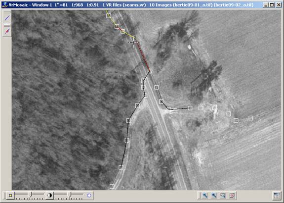
8. Select “0 Tog Snap” (F11) to turn snap mode on. Verify that snap settings are set to snap to line points.
9. In graphics Window 1, position the cursor at the location where you want the seam line to begin, and press button 1 to digitize a point on the existing strip to strip seam line.
10. If snap verify is on, then accept the snap point (assuming it found appoint in the existing strip to strip seam line).
11. A rubber-band line should be displayed from the point selected to the current cursor location.
12. Continue to use button 1 to digitize points along the seam line. Use the Zoom commands to zoom in and out as needed. Notice that as each new point is added to the seam line, the image display changes to reflect how the images will be merged along the seam line. Use option “3 Backup” if a point is placed in the wrong location.
13. If you are digitizing a large line and there are many images in the project, the image update process may take a few seconds each time a new point is digitized. If this is the case, use “9 Tog Update” to toggle the instant update feature. Using this method, several points can be digitized with update off, then update can be toggled once more to see the results.
14. The Mosaic application will normally determine the direction (horizontal or vertical), and the image sides (left, right, top, or bottom) for the seam line. The default settings can be changed using options 6-8 on the MenuKeys dialog. Each seam line has one direction associated with it, either horizontal or vertical. Each seam has two sides associated with it, one for each image or strip that it divides. Seam line direction and side may need to be changed manually, for example, to place seam lines along the edge of the project where there is no adjoining image or strip.
15. “0 Tog Snap” option can be used to turn snap mode on and snap to a point on the existing strip-to-strip seam line as the other side of the image is approached. A line that runs along the length of the overlap area between the two images, and begins and ends at points on the existing strip-to-strip seam lines should be displayed.
16. After snapping the final point, select “4 End” from the MenuKeys dialog to end and save the seam line. The previous MenuKeys dialog will be displayed. The next two images in the strip will be highlighted.
17. Repeat this process starting with step 5 until seam lines for all images in the strip have been placed.
18. Select “# End” on the Open Seam MenuKeys dialog to return the Main MenuKeys dialog.
19. Select “4 Tog preview” to view how the entire strip looks with all images cut to the seam lines.
NOTE 1: It may be helpful to temporarily turn off the seam line layer (Ex. LAYOFF 1) when viewing the image preview.
NOTE 2: Image preview mode does not reflect seam line feathering. This is only done in the final output stage.
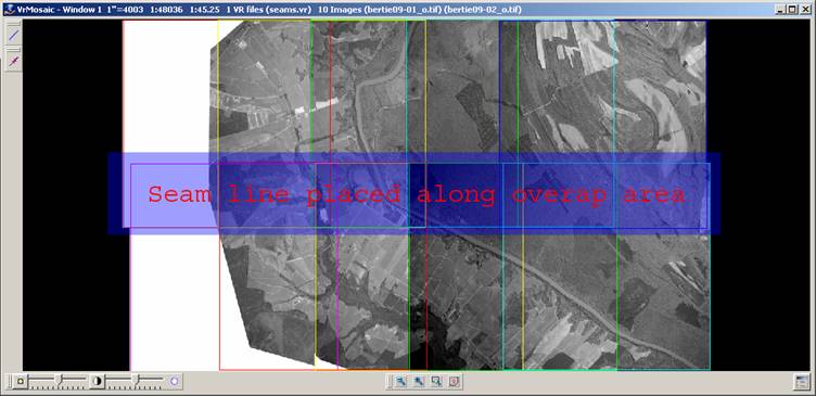
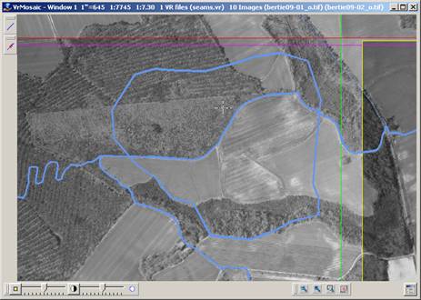
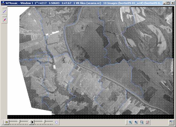
Finished seams for two image strips. Layout view shows area that will be cut from each image.
Collecting Using Closed Seams (Polygon Mode)
In this section of the tutorial, a closed seam line around a feature in a single image will be collected.
1.Select “8 Polygon Mode” from the MenuKeys dialog. This will display the Closed Seams MenuKeys dialog. The layout window will highlight the active image.
2.Image borders for all active images in the Layout window will be displayed. If not, type “ZOOA” in the command prompt area then select anywhere in the Layout window.
3.One of the images should be surrounded with a dashed highlight line in the Layout window. If this is not the correct image to place a seam line on, then point to and select another image using button 1 in the layout window.
4. In graphics window 1, zoom in close to the area where the seam line is to be placed. This is can be done using the Zoom Window (ZOOWIN) command or by using the Home and Page Down keys to center and zoom in to the area.
NOTE 1: Closed seam lines represent areas of the image that will be used in the final mosaic output. Multiple areas of a single image may be cut out and force them to be used in the final output. This may be needed if a feature that would normally not be used from an image because it is discarded by the normal open seam line, but it is required to force the feature to display.
NOTE 2: If using ZOOWIN, it will be required to end the ZOOWIN command before continuing to the next step.
5. Select the “Place Seam” button on the VrMosaic Main Steps dialog or select “4 Place Seam” from the MenuKeys dialog. This will display a new MenuKeys dialog that provides options for collecting the seam line.
6. In graphics Window 1, position the cursor where the seam line should begin and press button 1 to digitize a point. A rubber-band line should be displayed from the point selected to the current cursor location.
7. Continue to use button 1 to digitize points along the seam line. Use the Zoom commands to zoom in and out as needed. Because this is a closed seam line, once 3 points have been digitized, the display automatically shows a closing line going back to the first point. Use option “3 Backup” if a point is placed in the wrong location.
8. After all points have been digitized (there is no need to snap back to the first point), select “4 End” from the MenuKeys dialog to end and save the seam line. The previous MenuKeys dialog will be displayed, and the next image will be highlighted.
9. Repeat this process as many times as needed starting with step 3.
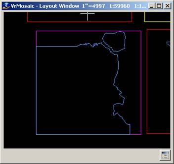
A single closed polygon has been added to upper left corner of an image. The layout shows that the image data will be taken from this image.
In this section of the tutorial, the seam line editing tools will be used to make changes to existing seam lines.
The standard mode for editing seam lines is very similar to using the VrOne Edit Line (EDILIN) command. In fact, the Edit Line Command (EDILIN) can be used to edit seam lines in VrOne or in VrMosaic without having the Mosaic application running. Using the standard mode editing tool built into the Mosaic application provide the added benefit of a real time image preview, along with the ability to move common points that are shared by multiple seam lines.
1. Select “2 Edit Seams” from the Main MenuKeys dialog (this is the first dialog displayed when staring the Mosaic application).
2. Point to an existing seam line graphics Window 1, and press button 1 (Id Seam). The cursor should snap to the nearest seam line point, and the Edit Seams MenuKeys dialog will be displayed.
3. Use the options displayed in the MenuKeys dialog to edit the line. Try moving points, deleting points, and inserting points. As the points are changed, the display will be refreshed to show how the images are affected by the new seam line location.
4. When finished, select “# End” (F12), to save the edited line and return to the previous MenuKeys dialog.
5. Repeat Steps 2-4 for other seam lines.
In dynamic mode, it is not required to identify a single seam line to edit as it is in standard mode. Instead, handles are displayed on all lines and point may be moved deleted or inserted at any time in a very intuitive manner. When the cursor is over a point handle, it will become solid. At this point press button 1 to move the point or button 2 to delete the point. If the cursor is not over a point handle, the nearest line segment will be highlighted. While a line segment is highlighted, any press of button one will insert a new point onto that line segment at the current cursor location.
1. Select “2 Edit Seams” from the Main MenuKeys dialog (this is the first dialog displayed when staring the Mosaic application).
2. Select “2 Dynamic Edit” from the Edit Seam MenuKeys dialog. All point handles will be calculated and displayed (there may be a delay if a large project is open).
3. Zoom in near a seam line so detailed image data is visible.
4. Place the cursor over a point that is shared by multiple seam lines. The 1st MenuKeys item should change to read “1 Move Pt”, and the second MenuKeys item (2 Del Pt) should be available.
5. Press button 1 to begin moving the point. The Move Point MenuKeys dialog will be displayed. This dialog has options for adding multiple points to the move group. For this tutorial, just a single point will be moved.
6. Move the cursor to a new location and press button 1. All seam lines that shared the common point are now changed to reflect the new point location. The image data is also changed to reflect the new seam line location. The Edit Seam MenuKeys dialog should now be displayed.
7. Place the cursor near the middle of a seam line segment, making sure it is not over an existing point handle. The closest seam line to the cursor should now be highlighted.
8. Press button 1 to insert a point at the cursor location. Notice that the seam line segment is changed to include new point. The image data is also changed to reflect the latest seam line data.
9. Place the cursor over the newly added point. The first MenuKeys item should change to read “1 Move Pt” and the second MenuKeys item (2 Del Pt) should be available.
10. Press button 2 to delete the point. Notice that the seam line segment is changed to remove the deleted point. The image data is also changed to reflect the latest seam line data.
In this section of the tutorial, the final output mosaic images will be created.
In this section of the tutorial, a single output image using manual mode will be created. Manual mode allows a manual selection of the bounds of a single output window. A new image will be written for the area selected.
1. Select the “Create Mosaics” button on the VrMosaic Main Steps dialog or select “5 Create Mosaics” from the MenuKeys dialog. This will display the Output MenuKeys dialog.
2. Select “1 Manual” from the MenuKeys dialog.
3. In graphics Window 1, digitize the lower left corner of the output window.
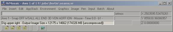
4. In graphics Window 2, digitize the upper right corner of the output window. Drag the cursor to select the upper right window corner, the VrMosaic main window status area will display the output image pixel dimensions and file size. The file size is only approximate, and reflects the raw size before compression. A confirmation MenuKeys dialog will be displayed. The VrMosaic main window status area will display the name of the Output File that will be created.
5. Select “1 Accept” to begin creating the output image. If the project settings are set for Image Balancing, then the images will be balanced first. The graphics window will display a moving scanline from the top to the bottom of the output area as a status indicator. When the output image is complete the VrMosaic main window status area will display the time it took to create the image. The Output MenuKeys dialog will display again, ready for a new output area to be selected (the same file will be overwritten unless the output file name is changed).
NOTE: Having feather mode on can significantly add to the processing time.
In this section of the tutorial, multiple output images will be created using batch mode. Batch mode requires that a sheet layout exist in the current VrOne seam file. The sheet layout procedure will be covered before continuing to the output steps.
In this section of the tutorial, a sheet layout to be used by the Batch Output mosaic process will be created. Sheet borders will be placed in Layer 2, and Sheet names will be placed in Layer 3 (the default layers in a new project). The grid command will be used to make the placement of the sheets easier.
1. Select Graphics->Set Grid Resolution from the pull down menu or enter SETGRI in the command prompt. This will display the Grid Parameters dialog box.
2. Type in 500.0 for a grid resolution.
3. Set grid type to points.
4. Set the grid display to "On".
5. Press "OK" to close the grid display dialog.
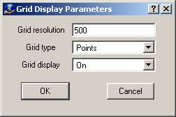
6. The Graphics window should show display grid points every 500.0 ground units.
7. Select Insert->Line from the pull down menu or type in or enter the Insert Line command (InsLin) in the command prompt. This will start the Insert Line command.
8. Enter SETLAY 2 in the command prompt. This sets the target layer to 2, the default layer for sheet borders.
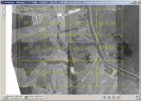
9. Using the grid points as a guide (the cursor will automatically snap to the grid), use Insert Line to digitize a square sheet in graphics window 1. Make the sheet the size that would be used in a typical project.
10. Select “# End” to end the Insert Line command.
11. Select Edit->Edit Line from the pull down menu or type in EDILIN in the command prompt. This will start the Edit Line command.
12. Select the upper left hand corner of the sheet line that was just placed.
13. Select “6 Line Functions” from the MenuKeys dialog.
14. Select “4 Copy Line” from the MenuKeys dialog.
15. Place copies of the sheet line next to each other. Place as many copies as needed to cover the output area with sheets. Having the grid points on will ensure that the sheets line up perfectly.
16. End the "Edit Line" command.
17. Select Insert->Text from the pull down menu or enter the Insert Text command (InsTex) in the command prompt. This will be used to place sheet name labels for each sheet that was defined in the previous steps.
18. Select “7 Enter Params” from the MenuKeys dialog. The Text Parameters dialog will be displayed.
19. Set the Layer to 3, the default layer for sheet names.
20. Set the width and height to large values such as 40.0 (the exact size will depend on the sheet sizes that were defined, but it should be large enough to be seen while viewing the sheet from an overview level).
21. Set the Justification X and Y to center. This is not necessary, but it makes it easier to position the text in the center of the sheets.
22. Set the Text value to SHEET1.TIF.
23. Press the “Ok” button to close the Text Parameters dialog.
24. Digitize a location in the center of one of the existing sheets. This will place the text label “SHEET1.TIF” in the center of the sheet.
25. Use “7 Enter Params” to change the sheet name to the next number (SHEET2.TIF), or type in txt=SHEET2.TIF.
26. Digitize a location in the center of the next sheet.
27. Repeat steps 25 and 26 until all sheets have a unique sheet name label inside them.
In this section of the tutorial, the sheets to output based on the defined sheet layout will be selected.
1. Select “Create Mosaics” on the VrMosaic Main Steps dialog or select “5 Create Mosaics” from the MenuKeys dialog. This will display the Output MenuKeys dialog.
2. Select “2 Batch” from the MenuKeys dialog. A dialog will be displayed providing information about the layers to search for sheet borders and sheet names.
3. Press the “Yes” button to continue. A new dialog will be displayed showing all of the sheets borders that were found along with the sheet names associated with each one.
4. Place a check mark beside each sheet to create.

5. Press “Ok” to begin creating the output images. If the project settings call for for Image Balancing, then the images will be balanced first. The graphics window will display a moving scanline from the top to the bottom of the sheet output area as each sheet is created. After the sheets have been created, the Main MenuKeys dialog will be displayed.
NOTE: Having feather mode on can add significantly to the processing time.