Vr Mapping |
ON-LINE REFERENCE DOCUMENTATION CARDINAL SYSTEMS, LLC |
Vr Mapping Definitions
“He spoke English but I didn’t understand anything he said.”
- Student after a training class
Active Workspace
Defines the current VrOne workspace into which new entities will be placed. Many operations, such as snapping, work on all opened workspaces but when entities are saved they can only be placed into one workspace.
VrOne allows more than one mapping command to be running at one time. Each command that is started suspends (or sleeps) the current command. When the top command is terminated, the next command is restarted or woken up.
For example:
Insert line is started and a road is being collected.
The operator sees a valve cover that he wishes to place now.
The insert symbol command is started.
The un-completed road edge disappears.
The operator places the valve cover and terminates insert symbol.
Insert line wakes up, the road edge re-appears and the instrument is driven to the last point collected on the line.
Up to 20 commands may be running in VrOne. Application overlaying supports all display commands, DTM and all mapping applications.
Construction Line
Line entities may be flagged as construction, which allows them to be turned off. This line description might be applied to hidden lines, reference lines, or other non-topological lines.
Dig
Dig is the act of digitizing a point. This may be to collect a data point or to identify an entity.
Defines the direction of North in reference to the graphics window. Many times it will be necessary to show north in a direction other than up. If you were to measure an angle from one of the vertical edges of the output device to the North arrow this would be the direction of North. The direction of North is measured clockwise from the Y-axis with zero being up.
Entity
An entity is a single piece of graphic data. An entity may be a line, symbol or text.
Function Keys
Function keys allow the assignment of entity parameters such as layer and graphic pointer to a map feature name. When this name is executed the defined mapping function starts and the defined parameters are assigned.
Graphics Window
A window used by VrOne to display map vectors and images. On Linux and Windows NT/2000, there may be up to eight windows opened at one time.
Key-ins
VrOne has a key-in area in the Main Window which allows commands to be entered at almost any time. Key-ins may be parameter modifications, VrOne commands, or macros.
Keyport 300
This is a 300-button touch pad from Polytel Computer Systems. Serving as a VrOne input device, VrOne key-ins, Function Keys, and Macros may be placed on the touch pad. Normally, the keypad is used when the Xyz digitizer is active, but may be used at any time.
Layer, Mode, Graphic Pointer
See Data Structure.
Line
A line is a collection of points that are connected by line segments. VrOne allows an unlimited number of points on a line. A Line Segment is one line consisting of two points that make up a line.
Line Font
A Line Font is a user-definable design for a line. Fence lines, tree lines and water lines are good examples of line fonts. The VrOne database stores lines as a series of Xyz vertices and a Line Font is fit along the line points when the line is displayed. Line fonting may be turned off.
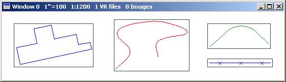
Line Box
When locking onto a line, you must be within the line box for that line to be considered. The line box is an imaginary rectangle that starts at the minimum North and East and ends at the maximum North and East of each line entity. A line box is often called a “Minimum Bounding Rectangle”. Following are some examples of line boxes:
Macros
Macros contain a group of VrOne key-ins, Function Keys or other macros. Macros may be named and executed as a key-in or menu board command.
Main Window
The main window used by VrOne. This window includes pull-down menus, key-in area, information area, coordinate display and the application (command) stack area.
Menu Board
A menu in which VrOne Function Keys, Entity parameters, and VrOne commands may placed. Items from the menu board may be selected from a Xy tablet. A smaller version of the Menu Board may be placed on the Polytel Keyport 300 keypad.
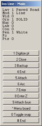
Menu Keys Window
A Menu Keys Window is a VrOne dialog box used by applications to display entity parameter information and the 12 button assignments. This dialog box appears when an application is started or woken up and disappears when that application is terminated.
A number line may be used to easily enter a group or range of numbers. A number line consists of a number or range of numbers separated by blanks, semi-colons, colons or stars. A dash between two numbers indicates a range of sequential numbers.
51-57 77 79 83-86
The above example would specify numbers 51, 52, 53, 54, 55, 56, 57, 77, 79, 83, 84, 85, 86. The maximum numbers that a number line may represent is 32001. The following number line examples will yield the same results:
51-57 77 79 83-86
51-57;77;79;83-86
51-57:77:79:83-86
51-57*77*79*83-86
51-57;77:79*83-86
NOTE: Blanks and commas are used to separate commands on a Vr key-in. When using a number line in a key-in, semi-colons, colons or stars should be used to separate the fields and commas should be used to separate commands. For example; to turn on a group of layers with a number line then execute a zoom all, the command might be: LayOn+ 10 20 30 40-50, ZooA
Orientations
VrOne supports several types of input orientations. These orientations are responsible for converting input machine coordinates to user coordinates. The three types of orientation are scratch, 2D least squares, and 3D least squares. Scratch and 2D Least Squares are used when a Xy digitizing tablet is active and Least Squares is used when an analog stereo plotter is active.
During the execution of VrOne, it is possible to switch the active input device with the command Digitizer XY (DigXy) or Digitizer Xyz (DigXyz). VrOne will automatically change the type of orientation used to accommodate the current input device. The orientation type may also be changed between 2D least squares and Scratch orientation when the active digitizer is a Xy tablet with the Toggle Dig Mode (TogDig) command.
Analytical stereo plotters and softcopy devices use other orientations and not the ones described above.
Orientation - Scratch
This orientation allows the use of a Xy digitizing tablet as a pointing device. The current scale of the digitizing tablet is the same as the scale of the output screen and changes as the viewing scale does. Scratch orientation is useful for cosmetic editing of map data and does not require a source manuscript to be present. This orientation is unavailable when a Xyz digitizer is active.
Orientation - 2D Least Squares
The two-dimensional least squares orientation should be used when digitizing map data from existing documents. This orientation spreads any map sheet error evenly between chosen control points. Before this orientation can be used, the program Orient 2D (or2d) must be executed to orient the map sheet and perform the least squares adjustment.
Orientation - 3D Least Squares
The three-dimensional least squares orientation must be used when a Xyz digitizer is used for input. Before this orientation can be used an orientation program must be executed to orient the current stereo model and perform the least squares adjustment.
Pen Table
The pen table allows the assignment of pen numbers to layers and modes. These pen numbers might represent graphic screen colors or pen numbers on a line plotter. Each of the four modes in every layer can be given a separate pen number. The use of pen tables in VrOne is optional. Each VrOne entity stores a pen number in its header.
Photo Name Format
Various processes such as aerial triangulation and model orientation require use of an image strip and photo number. These numbers are typically encoded in the image file name. Photo Name Format describes the method for extracting this information.
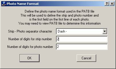
There are three parameters that make up the Photo Name Format: a separator character, number of digits in the strip number, and number of digits in the photo number. If the separator character is used to describe the format then the number of digits for the strip and photo numbers are not needed. If the file name does not have a separator character then the number of digits values must be used.
The photo separator character may be Underbar ‘_’, Dash ‘-‘, or Tilde (~) and the number of digits may be from 1 to 9. If the photo separator character is set to None then the Number of digits fields will be used. The following are several examples of the Photo Name Format.
Photo name: 23-56.tif
Photo separator character: Dash
Number of digits for strip number: any
Number of digits for photo number: any
Strip number: 23
Photo number: 56
Photo file name: 23056.tif
Photo separator character: None
Number of digits for strip number: 2
Number of digits for photo number: 3
Strip number: 23
Photo number: 56
Photo file name: 23056.tif
Photo separator character: None
Number of digits for strip number: 3
Number of digits for photo number: 2
Strip number: 230
Photo number 56
Prompting Units
At times, it makes sense to enter some parameters in as inches or millimeters at map scale. These include symbol and text sizes. This avoids re-entering these parameters for each map scale. Normally these values are converted to ground units before being applied to an entity. When a value is to be entered as inches or millimeters the hint (in|mm) will follow the prompt. Prompting units may be set in the VrOne configuration program.
Prompt Hint
When VrOne asks questions using a dialog box, it may offer some hints as to what type of parameter it is looking for. A prompt hint is in parenthesis after the question and will look as follows:
Search radius (ground)
In this example a search radius can be entered and its value should be in ground units.
Following are some commonly used hints:
Ground |
Ground units in feet or meters. |
in|mm |
A number in inches or millimeters determined by the prompting units. |
NumLine |
Number line. |
31 char |
Up to 31 characters |
Saved Coordinate
When Insert Symbol saves an entity, it saves its coordinate position as the Saved Coordinate. This coordinate can be used by applications such as Insert Text to place text based on the last symbol position.
Spline – Cubic – VrOne Line Mode 2
This spline is used in VrOne as a curved line display mode. The splined points are not stored in the VrOne file but are generated when this line is displayed. The curved line generated by this algorithm passes through all the points on the line.
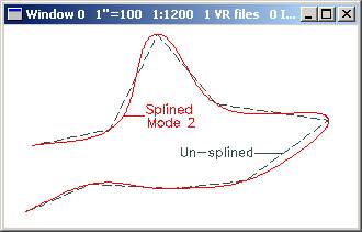
WARNING: A spline line may be aesthetically pleasing but may not be as statistically correct or accurate as a line that has not been splined.
This spline may be used to generate contours from the Digital Modeling application in VrOne. The points on the splined line are stored in the VrOne file. The curved line generated by this algorithm is an approximation and may not pass through all points on the line.
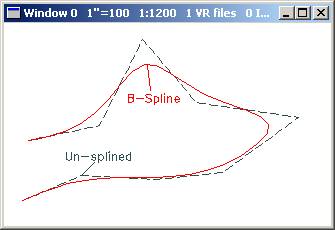
WARNING: A B-spline may be aesthetically pleasing but may not be as statistically correct or accurate as a line that has not been splined.
Snap
Snap is operation of attaching or locking to an existing entity in a VrOne file. Snapping may be used when collecting or editing an entity.
When snap is on and a point is digitized, VrOne searches all workspaces for the closest point to the one just digitized. If snap verify is on, then a tentative cursor will appear on the point snapped to. Pressing button 1 accepts the snap while button 2 will reject the snap and allow the user to try again, or button 3 will search for the next closest entity. A search radius may be specified to optimize the search procedure. If no points are found within the search radius, and "Ignore failed snaps" is set to "Yes", then the position digitized is used.
Target Scale
The target scale is the intended plotting scale of the VrOne file. This is also the scale in which map accuracy statements apply.
Text Font
VrOne supports the inclusion of twelve different text fonts in the same file.

Text Justification
VrOne supports ten justification positions. Text justification determines where the origin point of a text label will be. Each text label carries a X and Y justification as an parameter. The justification is a number from one to three. Text justifications are useful when a scale change is anticipated. For example, if all the text labeled in the center of objects were center, center justification, when the text was enlarged, the text would remain centered. The available text justifications are combinations of lower/center/upper and left/center/right. The text justification nine places the decimal point of a number as the origin.
The ten text justifications are as follows with the X justification listed first:
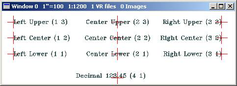
Decimal justification (4,1) is normally located between Center Lower (2,1) and Right Lower (3,1).
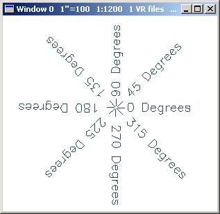
Text and Symbol Rotations
All text and symbol rotations are expressed in decimal degrees, counterclockwise, with the positive X axis as zero. Text and symbol rotations will always be referenced to the graphic data base coordinate system and not to the current screen rotation.
Workspace
A workspace is a VrOne file that has been opened and is ready for use. VrOne currently allows up to 256 workspaces to be opened at one time.
Xy Digitizer
An input device that outputs only Xy coordinates and has at least a 12 button puck or cursor. These devices are normally called digitizing tablets and may come in sizes from 12”x12” to 60”x48”. VrOne supports the scratch and 2D least squares orientation from these input devices.
Xyz Digitizer
An input device that outputs Xyz coordinates. These devices include analog stereo plotters such as the Wild B8, Kern PG2 and Zeiss E3, analytical stereo plotters such as the Zeiss P3, Wild BC2 and Kern DSR11, and softcopy software.
Analog stereo plotters support Least Squared transformations. Analytical and softcopy stereo plotters use their own input transformations.
Defines the origin for input elevations.
Xyz digitizer or active Z – The Xyz digitizer is a 3D input device such as a stereo plotter. The active Z is the current elevation and in changed each time a 3D input device is read. It is also changed by the Z command and when an entity is locked onto.
DTM surface if active – The elevation will be obtained from the current DTM surface if a model has been computed (RunDtm). The current Xy location is used to compute the Z.
Force Z value – The elevation will be set to the predefined Force Z value.
Point Drape (High/Low) - The active cursor is draped in the Z axiz to points such as LiDAR or Digital Surface Model (DSM) points. The High/Low Point Search is used to determine this Z value.
These parameters may be set using the Z Source (Zsou) dialog or key-ins.
When one line is attached to another or two lines are noded together, VrOne will display options for the action to be taken on the elevations of the two node points. The four Z rules are as follows.
Original Zs - When two lines are noded, the elevation of each node point is computed from the point in front and behind the node point. When one line is attached to another, the elevation is taken from the input device. This option does not modify the current elevations.
Mean Zs - Mean the two elevations from each line.
Z from 1st line - Set the elevation of the node point from the second line to the elevation of the node point from the first line.
Z from 2nd line - Set the elevation of the node point from the first line to the elevation of the node point from the second line.