Vr Mapping |
ON-LINE REFERENCE DOCUMENTATION CARDINAL SYSTEMS, LLC |
Workflow Overviews

Workflow
Camera Calibration File Preparation
Aerial Triangulation Workflow Overview
The Vr Mapping software offers solutions to many mapping tasks. Projects may require a variety of workflows to produce the final mapping products. The following are several workflows that may be needed. These are workflow overviews and are not intended to offer detailed processes. Please see the tutorials and other Vr Mapping documentation for more details on individual mapping operations.
Camera Calibration File Preparation
Task
Create camera calibration files for the Vr Mapping software.
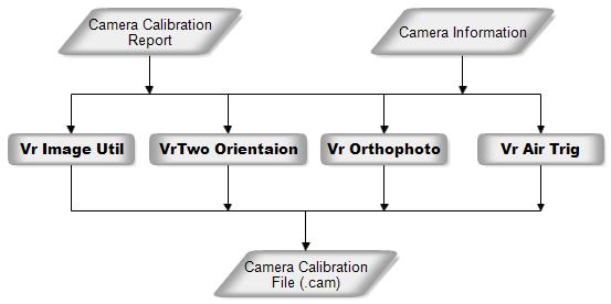
Images used in a mapping project require information about the camera that was used to capture the images. This information includes the photo size, focal length, calibrated principal point offset, fiducial units, fiducial coordinates and radial distortion values. If the images are taken with a camera that does not use fiducials such as the newer digital cameras, a camera calibration file is still required. More detailed information about the information in the camera calibration file can be found at Camera from the VrTwo Orientation program help page.
Task
Prepare images for use with the Vr Mapping software.
Images used for mapping require some parameter information before they can be used by the Vr Mapping software. This parameter information includes the Image Name Format (in which a strip and photo number can be parsed from the image name), the camera calibration (.cam) file name, the strip location or image rotation, and the pixel size of the image. When these parameters are assigned to an image, a Vr Image file (.vim) is created for each image on a project. The .vim file contains the parameters listed above along with the observations from the interior orientation, the six parameters that make up the exterior orientation (EO), and the pixel to photo transformation matrix.
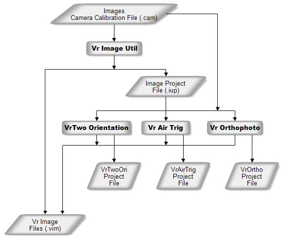
The Vr Image Utility program is normally the software used to create the output files. The image project (.iup) file that is created may be imported by the VrTwo Orientation program, the Vr Aerial Triangulation program, or the Vr Orthophoto program. It is possible to use VrTwoOri, VrAirTrig and VrOrtho to create the same parameters needed for each program. For example, if the workflow only required aerial triangulation and VrTwoOri and VrOrtho were not being used, the VrAirTrig program can be used for image preparation and VrImageUtil would not be required.
The Vr Image Utility program also provides other image utility operations including automatic interior orientation, batch image rotation, image format conversion, batch image pyramid creation and exterior orientation (EO) file format conversions. Please see the Vr Image Utility help page for more information about this program and image preparation.
Aerial Triangulation Workflow Overview
Task
Perform aerial triangulation point measurement, bundle adjustment and quality control.
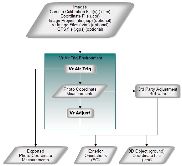
The process of aerial triangulation determines 3-dimensional object ground coordinates using several images of the same object taken from different positions. The VrAirTrig program performs project management, point measurement, and quality control. The VrAdjust program performs the computations (bundle adjustment) and calculates the object coordinates. The output from the aerial triangulation process is typically used as input to orient stereo models in VrTwo and/or provide image geometry for the orthophoto process in VrOrtho.
Aerial Triangulation Workflow Overview
The input coordinate file (.cor) is typically contains the base coordinate points (ground control) used to control the project. The output coordinate file (.cor) contains adjusted 3D coordinate positions for all measured points including pass, tie, and ground control points. Please see the Vr Aerial Triangulation (VrAirTrig) help section for more information about the aerial triangulation software.
Task
Collect vector data consisting of planimetric, topographic and elevation data from stereo models.
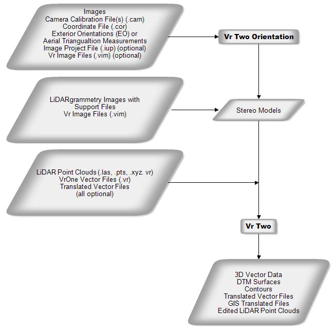
The workflow for VrTwo can include collecting vector and elevation (DTM) data. The editing of 3D vector and point (LiDAR) can also be part of the workflow. Non-image inputs into VrTwo include existing vector files and LiDAR data, which are displayed with 3D stereo imagery. Quality control for new and existing data is another key workflow option. The VrOne and VrTwo programs also provide data translations to other vector and LiDAR formats.
VrTwo Workflow Overview
Input images sources be from frame cameras, LiDARgrammetry (synthetic images created from LiDAR intensity) and Leica ADS-40 imagery. Please see VrTwo Orientation Getting Started with VrOne and VrOne-VrTwo help sections for more information on model orientations and the available tools for data collection, editing, batch processing, DTM processing, plotting and data translation.
Task
Create ortho rectified images and, optionally, mosaic and balance the images.
The ortho rectification process entails taking standard perspective images without uniform scale and transforming them into geographically referenced images with the perspective removed to provide uniform scaling. The ortho images can then be brought into a mosaicing application such as VrMosaic to tie the orthophotos together into a seamless image mosaic.
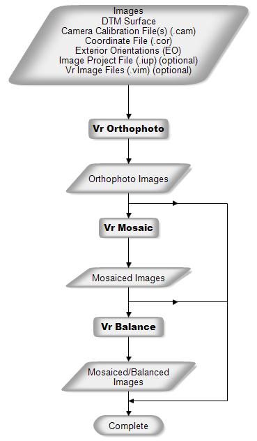
Orthophoto Workflow Overview
In order to perform the ortho rectification process, VrOrtho must have a images that have been fully oriented and a DTM ground surface for the area to be rectified. The DTM ground surface may be computed from standard VrOne vector files, containing points and break lines, or may be loaded from a VrOne surface file. If the DTM ground surface is specified as a VrOne vector file with points and break lines, then the surface will be computed as needed directly from the VrOne file(s). If a surface file is used, then the surface is loaded directly from the file, potentially saving a significant amount of processing time. Please see VrOrtho and VrMosaic for more information on these processes.
Task
Collect vector data from LiDAR point clouds and, optionally, perform quality control and correct errors in point classification.
Point clouds (LiDAR, DSM, vectors) may be displayed in several viewing environments. Existing Vr Mapping commands and workflows can collect and edit vector data. The 3D VrThree and 2.5D VrThree environments offer cursor draping, in which the 3D cusor is automatically draped onto LiDAR surfaces. These two environments also offer near and far clipping along the view direction for the additional isolation of data. The VrThree (VrLiDAR) data base supports up to 20 attributes for each LiDAR point. Input to and output from the VrThree (VrLiDAR) data base supports the LAS, Points and xyz formats.
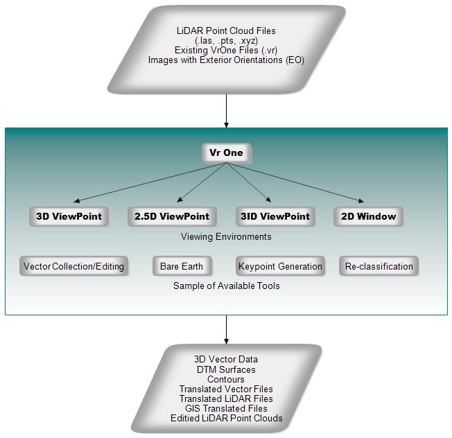
LiDAR Workflow Overview
VrThree (VrLiDAR) runs within the VrOne program, making the existing mapping commands and program features available when working with point clouds. The viewing environments include:
| • | 3D VrThree - LiDAR point data and vector data are displayed in 3D stereo. The user has the ability to collect and edit. Cursor draping and near and far clipping are available. |
| • | 2.5D VrThree - LiDAR point data and vector data are displayed in 2.5D (perspective or pseudo-3d) with the ability to collect and edit. Cursor draping and near and far clipping is available. |
| • | 3ID ViewPoint - Displays an un-rectified image and drapes LiDAR points onto the image along with vector data. Cursor draping is supported. |
| • | 2D Window - LiDAR point data and vector data are displayed in a standard 2D window. |
Point cloud (LiDAR, DSM) data may be displayed in the four environments listed above and in the VrTwo stereo environment. All environments support vector collection and editing and all have access to the commands and mapping features of VrOne. Please see VrThree (VrLiDAR) and VrOne - VrTwo for more information.