Vr Mapping |
ON-LINE REFERENCE DOCUMENTATION CARDINAL SYSTEMS, LLC |
Insert Orthogonal Line (InsOrt)
Type: Interactive Application
Inserts an orthogonal line in which results in a squared polygon based on the first two points read and subsequent segment points. The line may be closed back to the original line segment or left open. Each line segment assumes a 90 degree turn from the previous line segment. Each squared polygon is started by reading two points along one side of the polygon. This is normally the longest or most visible side. Subsequent points are read anywhere along following line segments. The polygon must be read in a clockwise or counterclockwise direction from the base line.
Since each line segment must turn 90 degrees from the previous, it is not possible to have un-squared segments using Insert Orthogonal Line. See Insert Square Line (InsSqu) for squaring ability with un-squared line segments. See also Insert Orthogonal Corner (InsOrc) which is similar to this application in which the polygon corners are read and allows un-squared segments.
Local Commands
Key-in |
Description |
Range |
LAY= |
Layer number |
1-10001 |
MOD= |
Mode |
1=Line 2=Spline |
GRP= |
Graphic pointer |
1-60 |
WID= |
Line width |
0-255 |
PEN= |
Pen number |
1-256 |
CON= |
Construction flag |
0-1 |
NGR= |
Non graphic pointer |
32 bit |
LNK= |
Link number |
32 bit |
FC= |
Feature code |
15 char |
DIG=x y z |
Digitizes point |
X Y Z |
FKEY=name |
Changes to function key parameters |
Function key name |
ZMOD= |
Sets the elevation mode |
0 = Interpolate 1 = Use elevation of first point 2 = Mean elevations |
Button Assignments
Ins Orthog - Main
Button |
Description |
1 Dig |
base pnt 1 – Digitize the first point of the base line. base pnt 2 – Digitize the second point of the base line. vertex pnt – Digitize a point on the next vertex. |
2 Close |
Closes the polygon to the first vertex. |
3 Backup |
Deletes the last point on the current line. |
4 End |
Ends and saves the current line without closing. |
5 |
|
6 |
|
7 |
|
8 |
|
9 |
|
* Menu board |
Makes selection from Menu Board. |
0 Toggle snap |
Toggles snapping on / off. |
# End |
Ends Insert Orthogonal Line. |
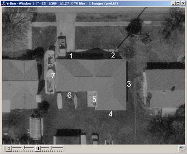
Points 1 and 2 are used to define the base line and are read on the longest side in this example. These points do not need to be read on the corners and are used to establish the azimuth of the squared polygon. Points 3 through 7 are observed anywhere on each side segment. The polygon may be read in clockwise or counterclockwise direction. Segments must be read in sequential order, each turning 90 degrees from the previous segment.
Vr Button Presses
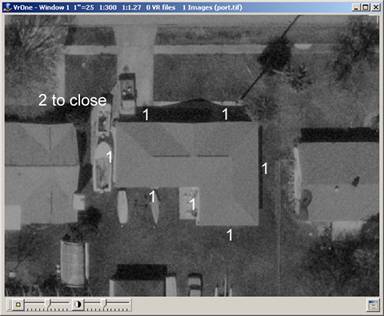
Observation of the base line and subsequent line segments are made with the Vr button 1. The Vr button 2 closes the polygon after the final line segment has been observed. The last line segment must be observed before Vr button 2 can be pressed. Pressing Vr button 4 allows a polygon to be left open. Before pressing Vr button 4, the final corner should be observed instead of the line segment so the location and end of the open line segment can be computed.