Vr Mapping |
ON-LINE REFERENCE DOCUMENTATION CARDINAL SYSTEMS, LLC |
VrTwo Orientation - Single Model Import of ISAT Measurements
Section 2 Importing Orientations
Section 3 Verifying Orientations
Section 4 Opening Model in VrTwo
VrTwo Orientation creates stereo image pairs (or models) for viewing in VrTwo and VrLite. Stereo models may be generated manually or by importing the results from various aerial triangulation programs. Orientations may be performed on a single model or multiple models in a batch mode. Models may be imported from aerial triangulation using exterior orientations or the measurements used to tie images and strips together.
Requirements to Complete a Single Model Import of ISAT Measurements
| 1. | Camera File - The camera file may either be imported or generated from a camera calibration report. |
| 2. | Ground Control File - The ground control file contains points obtained from sources like ground surveys. |
| 3. | Images - Images are raw, unedited, unmodified image files. |
| 4. | Correct Image Overlap - The image overlap must be on inside of images or in ortho mode. Images may need to be rotated to fulfill this criterion. Image rotation should be done before Interior Orientations are performed. If image rotation is required, this task can be performed in batch using the Vr Image Utility program. |
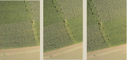
An example of photo overlap to the inside (ortho)
Creating or Editing the Camera File
New Camera (NewCam)
Allows the user to create and edit a new camera calibration file. Prompts user for the new camera's file name. Camera files in Vr Mapping have the .cam file name extension. See Edit Camera below for information on editing a camera file. If a preexisting camera file exists, this feature may not be needed.
Creating the Camera File
From the "Camera" dropdown menu, click on either "New Camera" or "Edit Camera".
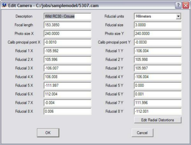
The Edit Camera dialog box
Creating or Editing a Control File
If one does not already exist, create a new coordinate file. From the "Coordinates" dropdown menu, click on "New Coordinate File". Please see VrTwo Orientation New Coordinate File for more information.
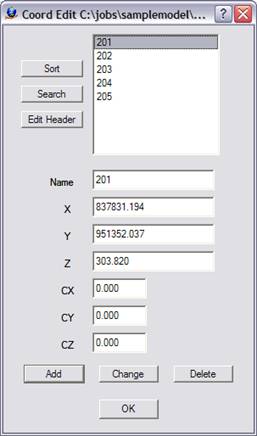
The Edit Control dialog box
If a control file exists and contains the PointName X Y Z fields, it can be used directly by Vr Mapping programs. Simply rename the file by replacing the file postfix with .cor. For example, if there were a coordinate file named TheCoords.txt which contained the PointName XYZ fields, it could be renamed TheCoords.cor and be used by VrTwo Orientation.
The following is an example of a contents of a coordinate file compatible with Vr Mapping:
201 837831.194130 951352.037020 303.8200
202 836399.079330 951266.642540 337.6800
203 837994.618340 950634.951710 299.6000
204 836711.670600 950565.198920 326.3200
205 836018.411470 950724.804370 309.2900
The first field is the point name followed by the X, Y and Z coordinates.
Creating or Editing the Project
The following steps create the project:
| 1. | Create a New Project File - From the "Project" dropdown window, click on either "New Project" or "Edit Project". |
| 2. | Add Coordinate File - Click the button to the right of the “Coordinates” box to add the coordinate file name. |
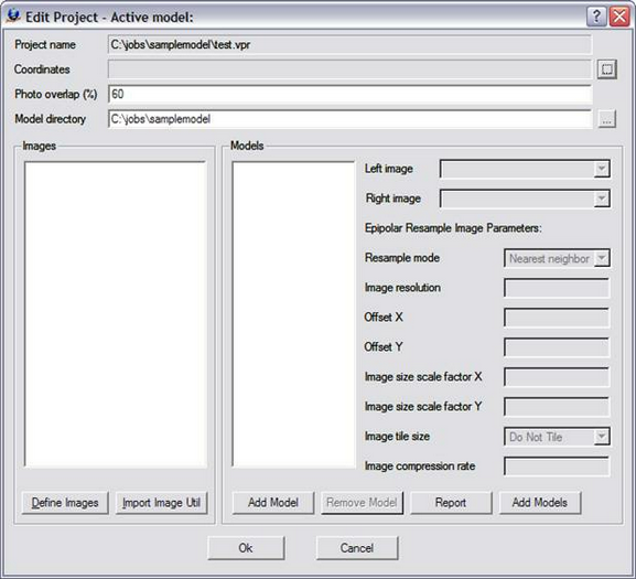
The Edit Project dialog box prior with no parameters defined
3. Define Images - Click the "Define Images" button in the "Edit Project" dialog box. The "Edit Project - Define Images" dialog box allows the definition of multiple image files. Each image file has a Photo Name Format, which are parameters that define the strip and photo number from an image file name. Strip direction, pixel size and the "Open in Layout" flag may also be defined for each image. The top portion of the dialog box is a template of these parameters. This template may be copied to an image or a group of images by selecting the desired file(s) then pressing the "Apply" button.
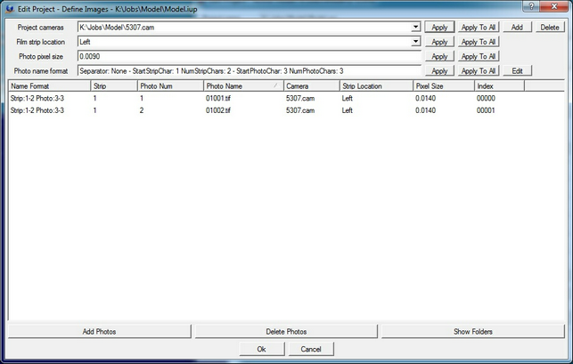
The Edit Project - Define Images dialog box
The following are descriptions of the parameters in the "Edit Project - Define Images" dialog box:
Project Camera
Project cameras (.cam) are assigned to individual images. Up to 10 camera files may be defined.
Film Strip Location
Defines the direction flight. For more information please see VrTwo Orientation - Film Strip Direction.
Photo Pixel Size
The photo pixel size is in the same fiducial units (millimeters, inches, or pixels) defined by the Camera file. If this value is unknown, it can be computed after reading three points in Inner Orientation at the bottom left of the Interior Orientation window.
Add Photos
Adds images to the project.
Photo Name Format
Sets the parameters that define the strip and photo number from an image file name. For more Information please see VrTwo Orientation - Photo Name Format.
4. Create Model Names
Click "Add Model" to create a new model. Pressing this button allows a single model to be added to the list of models. After the model is added, the left and right images must be selected and the epipolar re-sampling image parameters must be set.
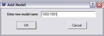
The Add Model dialog box
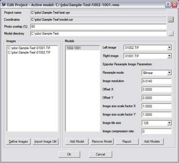
The Edit Project dialog box showing Model 1002-1001
Please see VrTwo Orientation - Project for more information.
Section 2 Importing Orientations
Part 1 Importing ISAT Interior and Measurement Orientations
| 1. | Select "Measurement Orientation - Single" from the "Import" dropdown menu. Click "ISAT Orientation". |
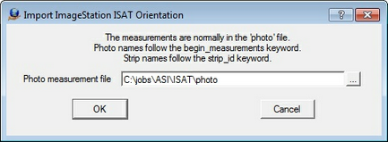
The Import dialog box requesting the photo measurement file
| 2. | Select the current location of the ISAT Photo file then press "OK". |
| 3. | Select the left and right photo names |
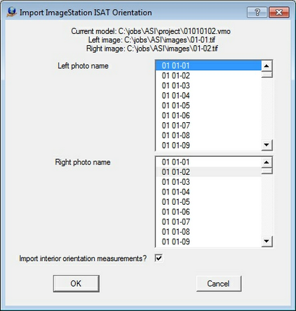
The Import dialog box for the definition of the left and right images that make the single model
3. Check "Import interior orientation measurements?" to include the Interior Orientations in the import.
4. Click "OK" to start the import process.
5. When asked to create epipolar images, move this dialog box off to the side until the results of the import are reviewed.
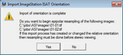
This dialog box is used to start the epipolar re-sampling process
6. Review residuals for Interior, Relative and Absolute Orientation.
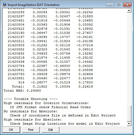
Dialog box showing the results after the Import process has completed.
Detailed results found in the results dialog box are shown below. The Total RMS values should be reviewed to verify that the import was successful. The following shows the results of the import of one model:
Import ImageStation ISAT Orientation
Left photo: 01-01
Right photo: 01-02
LEFT INTERIOR ORIENTATION
1 -0.0031 -0.0014
2 0.0079 -0.0045
3 -0.0013 0.0024
4 0.0043 0.0002
5 -0.0013 -0.0018
6 -0.0175 0.0034
7 0.0028 0.0013
8 0.0082 0.0003
Total RMS: 0.0063
RIGHT INTERIOR ORIENTATION
1 -0.0078 -0.0041
2 0.0052 -0.0060
3 -0.0011 0.0063
4 0.0059 0.0021
5 -0.0038 -0.0034
6 -0.0234 0.0026
7 0.0096 0.0002
8 0.0155 0.0024
Total RMS: 0.0104
Left photo: 01-01 - 54 points
Right photo: 01-02 - 66 points
RELATIVE ORIENTATION
47 common points:
Point X Left Y Left X Right Y Right Residual
21370307 76.838 -58.782 -12.314 -61.251 0.003
21370297 85.825 -65.500 -3.302 -68.079 0.002
21370317 83.828 -72.720 -5.238 -75.449 -0.001
21370322 74.673 -66.273 -14.482 -68.898 0.000
21419889 101.238 -97.322 13.071 -100.508 -0.006
21370632 65.755 -78.462 -23.557 -81.364 -0.001
21370720 26.827 -82.479 -63.209 -85.590 0.006
21370731 23.507 -88.196 -66.359 -91.422 0.003
21370828 -2.013 -69.690 -93.072 -72.640 -0.006
21370829 11.326 -94.092 -78.615 -97.468 0.002
21370830 11.604 -93.239 -78.348 -96.594 -0.001
21370845 15.827 -85.375 -74.218 -88.572 0.008
21370874 10.198 -79.657 -80.488 -82.770 0.004
21371323 -9.193 -98.001 -100.043 -101.521 -0.007
21420055 -19.133 -70.636 -110.413 -73.660 -0.003
21420036 21.328 -99.691 -68.570 -103.161 0.005
21370822 -1.640 -66.162 -92.843 -69.054 0.001
21371192 -9.285 -70.099 -100.290 -73.082 0.000
21371201 -17.042 -67.686 -108.466 -70.654 -0.001
21371281 -13.107 -97.296 -103.930 -100.807 -0.010
21420086 -10.797 -101.948 -101.661 -105.559 0.001
21419400 91.047 -29.798 2.132 -31.637 -0.002
21419398 72.444 -27.777 -16.808 -29.642 -0.012
21419505 93.223 -5.438 4.274 -6.807 -0.005
21419426 92.268 62.222 2.501 61.986 0.004
21419442 84.237 73.560 -5.805 73.451 0.006
21419552 95.450 66.551 5.779 66.399 0.006
21419425 89.979 48.838 0.392 48.386 -0.005
21420186 -6.042 -3.548 -97.488 -5.344 0.004
21420293 19.608 -12.081 -70.677 -13.892 -0.002
21420297 25.126 31.686 -64.865 30.626 -0.005
21420481 38.477 -22.157 -51.118 -24.075 0.013
21420504 29.273 7.850 -60.614 6.422 -0.000
21420522 43.859 36.102 -46.476 35.200 -0.003
21420190 0.187 51.721 -90.897 50.819 0.004
21420197 -13.728 81.544 -105.063 80.980 -0.004
21420211 2.223 69.050 -88.593 68.407 -0.000
21420303 19.382 55.809 -71.152 55.068 0.007
21420582 32.817 51.008 -57.818 50.275 -0.000
21420632 45.044 66.938 -45.236 66.510 0.000
21420219 -13.615 91.103 -104.906 90.653 0.006
21420436 26.879 103.898 -64.110 103.883 -0.013
21420784 89.093 -91.840 0.274 -94.964 0.006
21420841 91.747 29.262 2.144 28.497 -0.010
21420780 77.551 83.696 -12.886 83.704 0.001
21420881 106.351 60.663 16.796 60.480 0.005
314 91.421 18.120 2.028 17.154 -0.000
Total RMS error: 0.004
ABSOLUTE ORIENTATION
47 points for absolute
Residuals:
Point X Y Z
21370307 0.09121 -0.15773 -0.02738
21370297 0.47488 0.10994 -0.97399
21370317 -0.04852 -0.21873 0.28873
21370322 0.22286 -0.23109 -0.46047
21419889 0.17087 -0.13348 0.20637
21370632 0.24575 -0.16939 -0.42096
21370720 -0.01601 0.05894 0.07782
21370731 0.20960 0.01725 -0.32742
21370828 0.02789 -0.01199 -0.04135
21370829 0.31629 -0.01241 -0.41290
21370830 0.09911 0.02299 -0.10681
21370845 0.08229 0.05546 -0.11787
21370874 0.29524 0.04906 -0.43645
21371323 -0.27010 0.27783 0.41862
21420055 -0.07321 0.16779 0.16120
21420036 0.05955 0.09885 -0.02240
21370822 -0.26718 0.30929 0.50870
21371192 -0.24230 0.19606 0.42478
21371201 -0.17005 0.15885 0.33385
21371281 -0.14711 0.33623 0.30999
21420086 -0.11624 0.20739 0.31634
21419400 -0.01091 -0.13209 0.19414
21419398 -0.06127 -0.03391 -0.04427
21419505 -0.00556 -0.11936 0.16632
21419426 -0.18176 0.06995 -0.15057
21419442 -0.01296 -0.00932 0.07857
21419552 -0.09587 0.04550 -0.04733
21419425 -0.16139 0.05593 -0.17315
21420186 0.02421 -0.00699 -0.28813
21420293 0.00094 0.03051 -0.02242
21420297 0.00251 0.02407 -0.01883
21420481 -0.01819 -0.00449 0.10685
21420504 0.00363 0.01906 0.03392
21420522 0.02676 -0.01031 0.13852
21420190 -0.06447 -0.01538 -0.27607
21420197 -0.19395 -0.10707 -0.34161
21420211 -0.09441 -0.01924 -0.24198
21420303 -0.01282 0.02118 -0.07216
21420582 0.02323 0.01540 0.06513
21420632 0.04633 -0.00756 0.15262
21420219 -0.21874 -0.11458 -0.29132
21420436 -0.00565 0.01057 0.14462
21420784 0.22987 -0.46300 0.04320
21420841 -0.05226 -0.04525 0.03598
21420780 0.09409 -0.09974 0.40686
21420881 0.05460 -0.22477 0.52409
314 -0.26077 -0.01019 0.17800
Total: 0.11922 0.10034 0.22619
Total RMS: 0.29480
7. When the orientation results are acceptable, press the "OK button". Epipolar images will now be created from the results of the orientation. Epipolar images are rotation-removed, stereo-viewable images with a common scale. They make stereo viewing comfortable for the operator. The VrTwo Orientation main window will display status of the epipolar generation process on the bottom line. Epipolar results will be displayed in the same dialog that presented the Import RMS values

This dialog box is used to start the epipolar re-sampling process

VrTwo Orientation main window shown starting the epipolar process on image 10-02.tiff
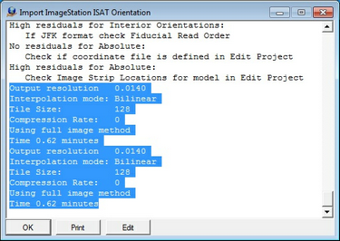
Results of the epipolar process.
Section 3 Verifying Orientations (Optional)
| 1. | Since measurements were imported, relative and absolute orientations may be viewed. To begin, select "Absolute Orientation" from the "Orientation" dropdown menu. This process can be used to verify the locations of the control, pass, and tie points in the Stereo Model. This process can also be used to visually inspect known ground control points for offset. |
| 2. | Click the first point in the results main window. To toggle roaming, press the Insert button on the keyboard. |
| 3. | To advance to the next point in orientation, press "Next point" (button 5). All visually identifiable ground control points can be verified using this method. |
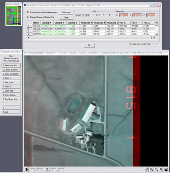
The VrTwo Orientation Absolute Orientation environment
Section 4 Opening Model in VrTwo
1.Start VrTwo.
2.Click File -> Open Model or use the Open Model (OpeMod) command. Navigate to the location of the project folder by double clicking in the far left hand box.
3.Double click the VrTwo Model (.vmo) file and press OK.
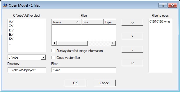
The Open Model dialog box
4 VrTwo will now generate pyramids for the epipolar images if they do not already exist.
5.Open a VrOne File by clicking on File -> Open Vr File or by using the Open VrOne File (OpeVr) command. Navigate to the project folder by double clicking in the far left hand box.
6. Double click the VrOne (.vr) file.
The stereo model should open. The stereo model and vectors should be seen on the screen. If the stereo window does not show a stereo image and vector,s try using the Drive Control (Cd) command. Typing "Cd 1" will drive to the first control point in the model. Please see the Getting started with VrOne/VrTwo tutorial, which covers basics of data collection and editing, for more information.

The VrTwo graphics window showing the stereo model (Anaglyph)