Vr Mapping |
ON-LINE REFERENCE DOCUMENTATION CARDINAL SYSTEMS, LLC |
Getting Started with VrOne/VrTwo
This document explains the process for creating maps with VrOne and VrTwo. It will walk through some of the steps to go from raw stereo image pairs to a finished mapping file. When this tutorial is complete, the user should be able to take raw stereo image pairs (either scanned or digital), orient them to a project coordinate system with VrTwo Orientation, collect vector data with VrTwo, and perform final cleanup, editing, and exporting with VrOne.
What is Vr Mapping?
Vr Mapping is a collection of software applications written specifically for creating digital maps. Vr Mapping software was designed for the Photogrammetry industry, and is the result of over 20 years of software development in this field. From its initial roots as an interface to stereo plotters, it has evolved into a full digital mapping toolset for multiple disciplines. Vr Mapping software has been used to map a variety of projects using stereo images, ortho rectified images, LiDAR data, or a combination of all three. Project types range from the mapping of Mount St. Helens, the exterior of the Space Shuttle, and the surface of Mars.
Two of Vr Mapping's main products are VrOne and VrTwo. A user with previous experience with CAD programs such as AutoCAD or Microstation would be familiar with VrOne and VrTwo. VrOne and VrTwo bear some resemblance to these other CAD systems but go beyond the standard CAD features to provide specific tools for Photogrammetry and other map making functions. There are over 200 mapping commands covering collection, editing, batch processing and more. Vr Mapping is also highly customizable with Function Keys, Macro Commands, and the Python programming language.
This tutorial does not go over all of the possible uses for Vr Mapping software, but focuses on two of the main programs required to create a basic map from aerial images. Although maps can be created using several different methods, such as tracing over ortho images and collecting from LiDAR data, this tutorial covers mapping from stereoscopic image pairs.
Software Tools Overview
There are many mapping products in the Vr Mapping suite, but this tutorial uses only four of them. Vr Image Utility will be used for initial project setup. VrTwo Orientation will be used to orient the raw stereo image pairs to your project coordinate system and to create stereo viewable epipolar images. VrTwo will be used to collect 3D mapping data from the epipolar stereo image models. VrOne will be used for final map cleanup and export.
Image Utility
Image utility contains many useful functions for dealing with images and should be the starting point before using VrTwo Orientation, VrOrtho, or VrAirTrig. Image utility provides the following main features:
| • | Image settings management (assigning camera settings, strip locations, and name formats) |
| • | Inner Orientation in manual and automatic modes. |
| • | Camera file creation and editing. |
| • | Batch image rotations in 90 degree intervals. |
| • | Batch image pyramid creation. |
| • | Batch image format conversion. |
| • | Image Pixel size computation. |
VrTwo Orientation
VrTwo Orientation is used to create stereo image pairs (or models) for viewing in the VrTwo and VrLite mapping software. Stereo models may be generated manually or by importing the results from various aerial triangulation programs. Orientations may be performed on a single model or multiple models may be oriented in a batch mode. The importing of models from aerial triangulation may be performed from the exterior orientations or from the measurements used to tie images and strips together.
VrTwo
VrTwo provides the ability to display stereoscopic images and collected full 3D mapping data from the images. Almost all of the features of VrOne are built into VrTwo. VrTwo provides two display modes which are static mode that displays fixed images with a moving 3D cursor and roaming mode featuring continuous roaming image with a fixed 3D cursor. Roaming mode is the preferred display method, and allows the operator to seamlessly move around large stereo image models without having to manually pan or re-center.
VrOne
VrOne is a powerful photogrammetric vector collection and editing package with image display capability. Photogrammetry today requires the mapping professional to deliver vector, image and digital terrain model (DTM) data as digital products. VrOne addresses many of the problems encountered in handling the collection, editing and plotting of vector, image and DTM data. Map updating and revision may also be performed with VrOne.
Mapping Work Flows
There are several work flow paths that can be taken to transform raw stereo pair images to a finished mapping product. The work flows depend on the type of starting images and how they are to be oriented to the project coordinate system.
Each work flow starts with raw images that contain no orientation information. The first part of each work flow is called model orientation. Model orientation is a three step process that involves Interior Orientation, Relative Orientation, and Absolute Orientation.
Three Step Orientation Overview
Interior Orientation
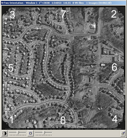
Aerial image showing eight fiducial positions
Interior Orientation determines the interior perspective of an image by assigning a coordinate system and applying the camera calibration. This is normally done with a least-squares adjustment between known and measured fiducial point coordinates. When using film, the interior orientation compensates for film shrinkage or expansion. Camera calibration information is required by Interior Orientation.
Relative Orientation
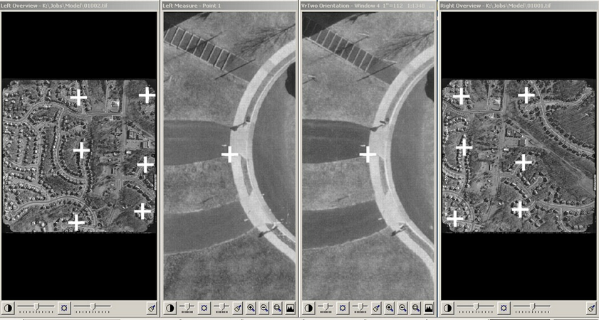
Relative Orientation with two overview windows and two measurement windows
Relative Orientation aligns the two images of a stereo pair so they can be viewed in 3D. This is done by observing common points on each image, in effect, tying the images together. Another least-squares adjustment is performed on these observed points. An Interior Orientation is required by Relative Orientation.
Absolute Orientation
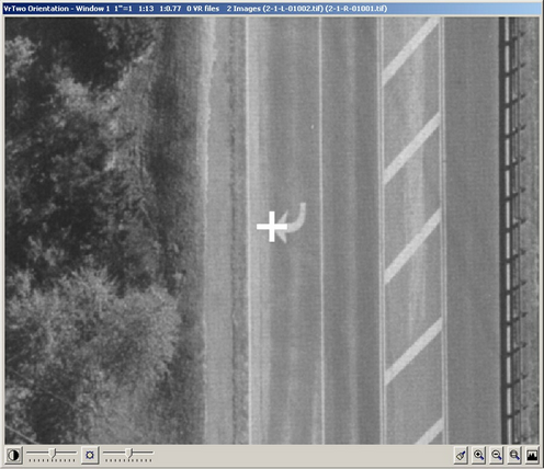
Control point measurement in Absolute Orientation
Absolute Orientation defines the transformations between the model space that was achieved with relative orientation and a known ground or object space coordinate system. Again, anther least-squares adjustment is performed to obtain these transformations. In this process an Exterior Orientation is created for each image. A Relative Orientation solution control point file in the project coordinate system is required by Absolute Orientation.
The results of orientation are stereo viewable epipolar image pairs, model definition files (.vmo) , and orientation (.orp) files. The .vmo files are opened in VrTwo using the Open Model (OpeMod) command in order to view the stereoscopic images. The .orp files have the same name as the left epipolar image file with the .orp extension, and contain the final orientation data to be used by VrTwo.
Below are examples of several work flow scenarios.
Work Flow Scenario One - Single model Orientation
The first type of work flow does not require any processing outside of the Vr Mapping tools. This is normally used for small projects that only require a few stereo models to be set up and have ground control consisting of at least two horizontal points and at least three vertical points.
| 1. | Interior orientation - Images with fiducials: Use Vr Image Utility to define images and perform automatic Interior Orientations. Images without fiducials: Use Image Utility or VrTwo Orientation to define images and perform corner Interior Orientations. VrTwo Orientation may also be used to define images and perform manual interior orientations or Corner Interior Orientations. |
| 2. | Relative orientation - Use VrTwo Orientation to create model definitions and measure common points between left/right images on each model. This process will generate stereo viewable epipolar images. |
| 3. | Absolute orientation - Use VrTwo Orientation to measure control points in stereo to compute the final model parameters. |
| 4. | Collect mapping data in VrTwo - Use VrTwo to open the model files produces by VrTwo Orientation, and place mapping features from a stereoscopic 3D view. |
| 5. | Clean mapping data and prepare for delivery - Use VrOne to perform batch clean up operations, generate contours if required, and put together final map sheets and translate the mapping data if needed. |
Work Flow Scenario Two - VrAirTrig Measurement and Import
The second type of work flow requires processing by VrAirTrig and VrAdjust or a third part aerial triangulation adjustment application. This is normally used for larger projects where single model setups are not practicable.
| 1. | Interior orientation - Images with fiducials: Use Vr Image Utility to define images and perform automatic Interior Orientations. Images without fiducials: Use Vr Image Utility or VrTwo Orientation to define images and perform corner Interior Orientations. VrTwo Orientation may also be used to define images and perform manual interior orientations. |
| 2. | Aerial triangulation - Use Vr Aerial Triangulation (VrAirTrig) to measure points on all images and run a block adjustment using VrAdjust or a third party adjustment application. VrAdjust runs inside VrAirTrig while adjustments with other third party adjustments may be done my exporting the measurements. |
| 3. | Import AT measurements or exterior orientations - Use VrTwo Orientation to import the measurements created in VrAirTrig, or import the exterior orientations produced by VrAdjust or other third party aerial triangulation adjustment application. This will produce stereo viewable epipolar images along with exterior orientations for each model. |
| 4. | Collect mapping data in VrTwo - Use VrTwo to open the model files produces by VrTwo Orientation, and place mapping features from a stereoscopic 3D view. |
| 5. | Clean mapping data and prepare for delivery - Use VrOne to perform batch clean up operations, generate contours if required, and put together final map sheets and translate the mapping data if needed. |
Work Flow Scenario Three - Third Party AT Measurement and Import
The third type of work flow requires AT measurement and processing by third party aerial triangulation application. This is normally used for larger projects where single model setups are not practicable.
| 1. | Interior orientation - Images with fiducials: Use Vr Image Utility to define images and perform automatic interior orientations. Images without fiducials: Use Vr Image Utility or VrTwo Orientation to define images and perform corner interior orientations. VrTwo Orientation may also be used to define images and perform manual interior orientations. NOTE: This step may be skipped if you are importing a third party aerial triangulation format that supports Interior Orientations. |
| 2. | Import AT measurements or Exterior Orientations - Use VrTwo Orientation to import the measurements or exterior orientations produced by the third party aerial triangulation adjustment application. This will produce stereo viewable epipolar image along with exterior orientations for each model. |
| 3. | Collect mapping data in VrTwo - Use VrTwo to open the model files produces by VrTwo Orientation, and place mapping features from a stereoscopic 3D view. |
| 4. | Clean mapping data and prepare for delivery - Use VrOne to perform batch clean up operations, generate contours if required, and put together final map sheets and translate the mapping data if needed. |
Vr Mapping Concepts
This section will describe several concepts used in the VrOne and VrTwo programs.
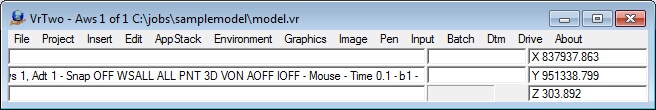
Main Window
The Main Window in VrOne and VrTwo contains the command pull down menus, a key-in area, two information areas, the application (command) stack, a progress bar and the coordinate display. Commands names may be typed into the key-in area at almost any time. The system mouse must be in the Main or Graphics window for keystrokes to go into the key-in area.
On the border of the Main Window is shown the active workspace, the number of workspaces currently opened and the current VrOne file that is open.
Graphics Window
The VrOne and VrTwo graphics windows display vectors and images. At the top of the window is displayed the window number, the scale of the window, the number of VrOne files opened and the number of images that are open. Also displayed is the image pyramid scale (i.e. 1:3.10) and the first two image names. In the lower right corner of the graphics window is a push button that allows the setting of the display of images, image names and image edges.
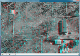
Graphics window displaying a stereo model (Anaglyph)
Menu Keys Dialog
The Menu Keys Dialog window is displayed by most interactive commands. The title of the dialog displays the currently running command name and the current command state. The top area of the dialog contains the entity parameters. This information is command dependent and normally shows where the data is to be stored on insert commands or where the data came from on edit commands. The bottom area contains the menu key buttons. These show what functions are assigned to the 12 menu key buttons. These keys are normally mapped onto an input device such as the keypad on a digitizing tablet cursor, or the button on a 3D input mouse. They are also mapped onto the 12 function keys on a standard keyboard.
VrOne Vector Files
VrOne and VrTwo store mapping data in VrOne vector database files. These vector files use a .vr extension. The VrOne database is an entity based non-topological structure. Although the database contains some non-graphic and extended information other CAD systems do not, it cannot be considered a true Geographic Information System. It can however prepare vector data for accurate translation to GIS and other CADD systems.
Vector support files
Although each VrOne/VrTwo vector file can be considered a stand-alone database file, there are some support files required for displaying symbols and line fonts. An external pen table may also be used for controlling color by layer. The size of the file is operating system dependent. A VrOne/VrTwo vector file holds five different entity types which are Lines, Splined lines, Symbols, Text, and Points (LiDAR).
Creating new vector files
There are two methods for creating new vector files. The first method uses the "Open Vr Files" dialog, and prompts you for Target Scale and other file header settings. The seconds method is faster, but by default does not prompt for file header settings.
To create a new VrOne File and specify the target scale settings, follow these steps:
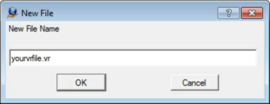
| 1. | Click on File then Open VR Files, Then Click on New File. |

The Open File dialog box used by Vr Mapping
| 2. | Specify your desired file name for your new VrOne file. |
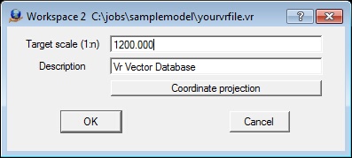
| 3. | Set your Target Scale and Vr File Description. See next section for details on the Target scale settings. |
Workspaces
Workspaces are used by VrOne and VrTwo to manage multiple vector files. VrOne/VrTwo allows you to open multiple vector files and view them simultaneously, and each vector file is assigned a unique workspace number.
Active Workspace
Although multiple workspaces may be open at one time, only one workspace is considered active. Only the currently Active Workspace will store new entities. VrOne/VrTwo provides several methods to quickly switch the Active Workspace. VrOne/VrTwo also provides tools for merging workspaces, copying and moving data between workspaces, cutting out data to new workspaces, and more. An inactive workspace may be refereed to as a reference file in other mapping systems.
Target Scale and Prompt Units
Each VrOne/VrTwo vector file contains a Target Scale setting that is defined as the intended plotting scale or project scale. The Target Scale also controls the size of new symbols and text entities. You may configure the Prompt Units in the Vr Configuration program to be inches or millimeters. In VrOne and VrTwo the symbol and text sizes are entered as inches or millimeters at the Target (or plot) Scale. For example, if working in a vector file with a Target Scale set to 1:1200 (1"=100') and Prompt Units set to inches, a symbol placed with a radius of 0.1 will be drawn at radius of 10.0 ground units. The sizes are computed at placement time. If the file target scale is changed later, then symbols and text may be need to be rescaled using the Global Change command. Line Fonts such as tree lines and fence lines will be re-scaled automatically if the Target Scale is changed.
Symbol Radius and Text sizes
In many cases, items such as symbol and text sizes are specified as units at Target Scale. All symbols are stored with a radius of 1.0 and the size of the symbol is applied when the symbol is placed. A symbol radius may be defined as 0.08 of an inch and when placed with a Target Scale of 1:1200 (1"=100') would result in a ground radius of 8.0.
Transform and Shift Workspace
Vr has two primary commands for changing the coordinates in existing vector files. Transform workspace performs a 2-dimensional transformation on one or more vector files. Transform options include translate, rotate, and scaling. Shift workspace performs a simple 3-dimensional shift of one or more workspaces. See the Transform Workspace and Shift Workspace documentation for more details.
Symbols and Line Fonts
VrOne and VrTwo stores symbol definitions and line fonts in a single symbol definition file. The symbol files use a .sym extension. Vr Mapping ships with a default symbol file containing sample symbols and line fonts, but it is an easy task to add and modify symbols and Line Fonts.
Managing Symbols and Line Fonts
The Manage Symbols (ManSym) command is used to view and manage existing symbols and Line Fonts. The Symbol Manager dialog displays all symbol and line font definitions in the current symbol library. The user can page through all of the symbols in the library, or jump directly to a specified symbol. After selecting a symbol, the user has the option to change the symbol name and size, create a new symbol, edit the symbol, clear the symbol, or copy the symbol. The symbol library can be saved to a new name. Existing symbol libraries can be loaded and edited, and new symbol libraries can be created. The number of symbols displayed per page and the symbol display size may be customized. Double clicking on a symbol will start the Insert Symbol or Insert Line command with the graphics pointer set to the selected symbol. See the Manage Symbols document for more details.
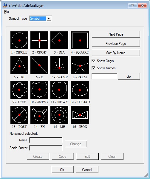
Manage Symbols and Line Fonts
Creating a New Symbol or Line Font
New symbols or line fonts may be created by identifying existing line entities. These entities will be used to make a Symbol or Line Font.
The size of the lines to be used is not important during creation. Line fonts use a line font length and are scaled at plot time. Symbols are stored with a radius of one and are scaled at plot time. Since VrOne files contain a target scale, one symbol library may be used for many map scales. See the Create Symbols document for details about creating Symbols and Line Fonts.
Programming VrOne/VrTwo
There are three ways to program the VrOne/VrTwo mapping environment. These methods include Macros, Function Keys and the Python programming language. Although VrOne/VrTwo is delivered with many powerful tools the ability to program the systems gives users the ability to tune and extend the system.
Function Keys
Function Keys are the most important aspect of VrOne/VrTwo data collection. Taking the time to properly set up function keys before a project has started will save hundreds of hours of production time.
Function Keys are the method of making a mapping system out from a CAD system. For example, instead of using Insert Line to place a road, the operator will used a Function Key such as PavedRoad. PavedRoad will assign all the proper attributes and behavior to Insert Line and start it.
Function Keys reduce the amount of knowledge the mapping professional needs to know about VrOne/VrTow. They simply choose the feature they want to collect and begin collecting vector data.
Entering its name or function key number may start a function key. These names or numbers may be keyed in, placed in macros or even placed in other function keys.
The name of the Function Fey file to use must be set in the VrOne configuration program (VrCfig). It is possible to have multiple function key files but only one can be active at a time.
See the the tutorial on Function Keys or the tutorial on the Function Key On End Command for details about setting up new and editing Function Keys.
Macros
Macros give the ability to execute a group of VrOne commands as a user-defined word or character. Macros can execute VrOne commands, function keys and other macros. Several uses of macros might be to condition snap parameters and with 30,001 layers, it is useful for turning groups of layers on and off.
A macro can be used for simple functions like toggling in and out of roaming. The following Macro allows the user to type the letter R to issue the Toggle Roam (TogRoa) command. This saves the user the additional keystrokes that would be required to type the full command. To add this macro type the name in the Name Field then commands in the main window. When done click the add button at the bottom.
The AddFile button can be used to define file names by selecting them from a dialog box. The resulting file name will contain the drive letter and file path.
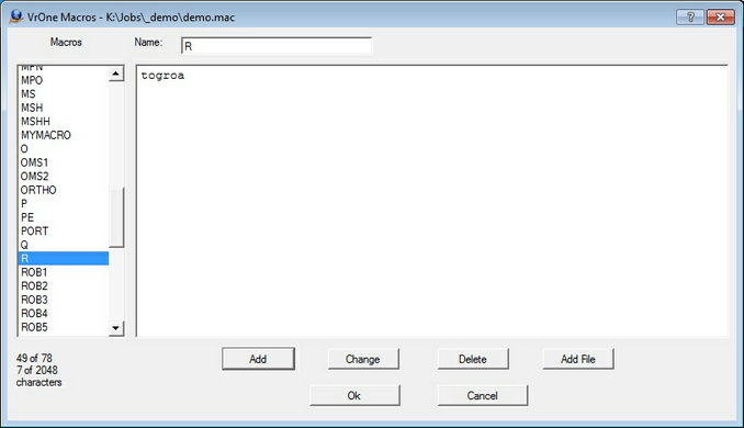
Edit Macro dialog
Python Programming
Python is an object-oriented scripting language. Its design mixes software engineering features of traditional languages with the usability of scripting languages. It is possible to write Python scripts that interface with VrOne through VrOne/Python classes. This interface allows full access to reading and writing the VrOne database and the access to interactive editing. Python is a great way to extend the capabilities of the existing VrOne collection applications. For example, a Python script could be written to place symbols on the ends of a line each time the line is saved. See the Python Programming document for more details.
Tutorial Overview
For this tutorial, a sample stereo model that has already gone through the orientation process will be used. The sample model was produced using Work flow Scenario One - Single Model Setup.
To learn more about the orientation process, and follow the steps to create the sample model from scratch, then please see VrTwo Orientation single model orientation .
Tutorial Walk Through
Downloading the Sample Data
To get started, download some sample data and install it to your local machine. The sample data for this project can be download at the following address.
http://vrdownload.cardinalsystems.net/downloads/sample-data/gettingstartedmodel.exe
Please contact Cardinal Systems for the username and password for this download.
Install the Sample Data
Run the gettingstartedmodel.exe file. This will install the sample data into c:/jobs/samplemodel.
The sample data consist of the following files.
| • | Two Epipolar Images |
| • | Orientation file .orp |
| • | Model file .vmo |
| • | VrOne/VrTwo Vector file .vr |
| • | Macro file .mac |
Now that the sample data has been installed, you will use VrTwo to open and display the stereo images.
Starting VrTwo
| 1. | Double click on the Vr Mapping folder on your desktop. |
| 2. | Double click on the VrTwo Icon in the opened Vr Mapping folder. |
Once opened, the VrTwo Main Window is displayed along with one or more graphics windows as shown below.
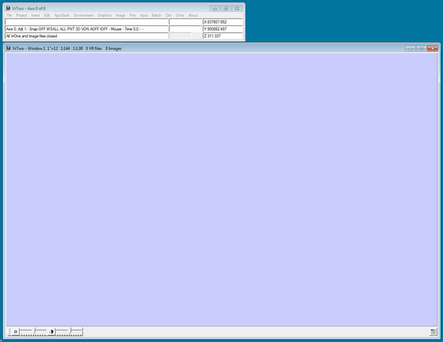
VrTwo Main Window and Graphics Window with no model or VrOne vector file open.
The sample stereo model may now be loaded into VrTwo.
Loading Sample Model Into VrTwo
| 1. | Click on File then Open Model. This can also be done by using the Open Model (OpeMod) command. |
| 2. | Navigate to C:/jobs/samplemodel/ |
| 3. | Select 2-1.vmo then click OK. |
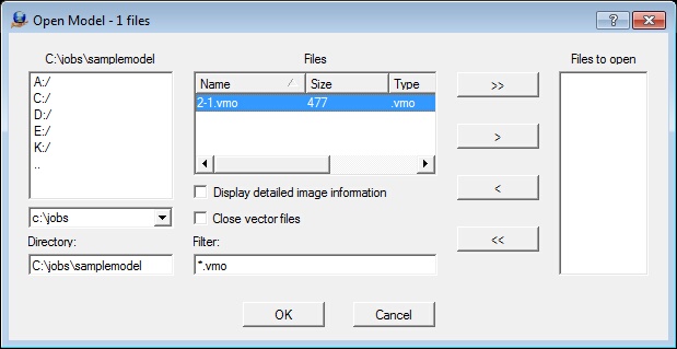
Opening a model in the Open Files dialog box
A stereo model should now be displayed in the VrTwo graphics window. If using stereo shutter glasses with an emitter, you should see the emitter light turn on, and the content should be viewable in 3D using the shutter glasses.
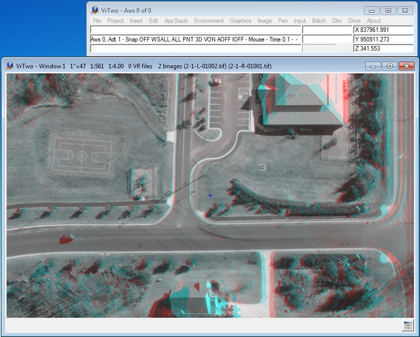
VrTwo stereo model (Anaglyph)
The Toggle Roaming (TogRoa) command is used to switch between static and roaming modes.
Opening the Sample Vector File
The sample data provided includes a sample line work file named model.vr that may now be opened.
| 1. | Click on File then Open VR Files or use the Open Vr Files (OpeVr) command. |
| 2. | Select c:/vr/samplemodel/model.vr then click OK. |
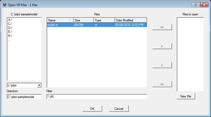
Opening a VrOne/VrTwo vector file in the Open Files dialog box
This concludes the step by step part of this tutorial. The remaining sections describe different methods for collecting and editing data now that you have a stereo model loaded.
Collecting Data
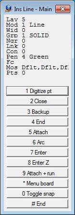
Insert Line Application
The Insert Line (InsLin) application allows multiple point lines where the operator determines the location of the points. To start Insert line, select Insert->Insert Line or type use the Insert Line (InsLin) command.. Pressing button 1 (left mouse click on system mouse) will digitize points. Press button 4 (F4) to end the line. See Insert Line for more information on this application.
Inserting Lines by Function Key
Most users will digitize data by using predefined function keys. For example, to digitize the edge of a road, the user would start the "Road" command instead of starting Insert Line. Starting the Road command could be done by typing in a number, typing in "Road", or selecting it from an input device. The Road command as defined in the function key definitions, would set all the correct attributes for Insert line. Once in the Road command, all of the normal Insert Line features apply: Press button 4 (F4) to save the current road and begin a new one, or press button 12 (F12) to exit the road command completely. See Insert Line for more information about this application.
Below is configuration for the road function key. Function keys can be edited by using the Edit Function Keys (EdiFun) command or by clicking on Input / Edit Function keys.
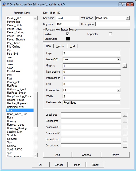
Edit Function Keys dialog box
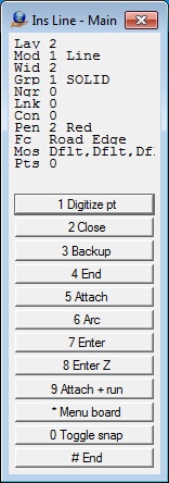
Following is the Insert Line Menu Keys dialog box that was started from the Roads Function Key.
Other Applications That Can be Used for Inserting Lines in VrOne/VrTwo.
Insert Fly Line (InsFly)
Digitizes a line in "fly" mode in which the line is drawn freehand in stream mode. Places the proper number of points on the line as determined by user define parameters to make the line smooth. This is useful for digitizing contours, water lines and break lines. A manual mode may be entered when in stream digitizing mode which allows points to be digitized manually. See Insert Fly Line for more information about this application.
Insert Square Line (InsSqu)
This application inserts a line and squares the line to one of several user-defined parameters. Supports squared and un-squared segments and helps with hidden corner placement. Lines may be closed and squared or left open and squared. Lines may also be squared to and attached to other lines with Insert Square. See Insert Square for more information about this application. Two additional squaring applications are available for squaring lines which are Insert Orthogonal Line (InsOrt) and Insert Orthogonal Corner (InsOrc).
Insert Parallel Line (InsPar)
Places parallel lines from a user-defined baseline. The distance from the base line may be specified by a digitized point or by entering an offset distance. The elevation difference from the base line or previous line may also be specified. Parameters for the new line may be obtained from the base line or from a user-defined Function Key. See Insert Parallel Line for more information about this application. Two additional application are available for parallel lines which are Insert Multiple Parallel Lines (InsMul) and Batch Offset (BatOff).
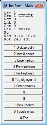
Insert Symbol Application
The Insert Symbol (InsSym) application allows the placement of graphic symbols from the symbol library. Each symbol is assigned a graphic pointer number that coincides with a symbol in the currently loaded symbol file. The symbol file is defined in Vr Configuration under the Vector settings dialog. See Insert Symbol for more information about this application.
There are three main modes when Digitizing symbols.
| • | A one-point symbol will be placed with one digitized point using the current radius. |
| • | A two-point symbol will be placed with two digitized points. The first point is the symbol's origin and the second is the radius. If symbol interactive rotation is on then the scaling and rotation of the symbol is handled as a single step. |
| • | A three-point symbol can be placed by digitizing three points along the edge of the symbol. The three-point symbol is useful for placing items such as large tanks with a symbol where the center of the tank cannot be determined. |
Button 6 (F6) toggles the symbol rotation mode. When the symbol rotation mode is on the symbol will be placed by digitizing two points. The first point defines the symbol origin and the second is the symbol rotation. This is useful when placing symbols such as poles with directional ticks. The rotation of these type or symbols normally changes between each symbol. If the number of points to use when placing a symbol is set to two then the scaling and rotation of the symbol is handled as a single step.
Below is the Parameters dialog box for Insert Symbol. This can be accessed by pressing button 7 (F7) while running Insert Symbol.
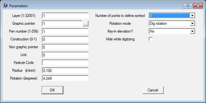
Insert Symbol (InsSym) parameters dialog box
Inserting Symbols by Function Key
When collecting data, symbols will typically be placed by starting a predefined Function Key. For example, rather than starting Insert Symbol (InsSym), pressing button 7 (F7) then changing the graphic pointer and other parameters, it would be possible to just type spot to start the "Spot Elevation" Function Key. This Function Key would start the proper VrOne/VrTwo application and assign all the needed attributes and conditions to collect this feature type.
Below is the setup for the Spot Elevation Function Key . Function keys can be edited with the Edit Function Key (EdiFun) key-in or by clicking on Input -> Edit Function Keys. See the Function Keys tutorial for more information about setting up these keys and see the On End tutorial for more information about using the On End Command which is available in the Function Key definition.
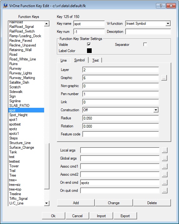
A Function Key to place Spot Elevations
Insert Text Application
Insert Text (InsTex) is designed to be run interactively or to be launched from a Function Key or Macro. When used interactively, a rich set of options enable precise text placement in most situations. When run from another function key, options allow the application to be started and a text label to be placed without user intervention. Text labels may be typed in using a dialog box, keyed-in from the key-in area or from a text file.
Running Insert Text interactively can be done by starting the Insert Text application (InsTex) or clicking on Insert -> Insert Text.
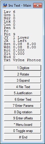
Below is the parameters for inserting text, this dialog box can be viewed by pressing button 7 (F7) while Insert Text is running.

Inserting Text from a Function Key
As with other insert functions in VrOne and VrTwo a Function Key that predefines the application to start and the attributes and parameters will be used for inserting text. See Edit Function Keys (EdiFun) for more information about Function Keys.
The On End Command
Insert Text (InsTex) may also be called from another Function Key's "On End" command. This is useful for features like adding text and elevations when placing Man Holes. In the example below, the user would type "Mh" or "1256" to start the following Function Key. This function key would begin the "Insert Symbol" command and when the symbol was digitized, the Function Keys to place the text "MH" and the elevation would be started. Once the two additional text labels were placed the Function Key would return to placing the symbol. See the On End Command tutorial for more information.
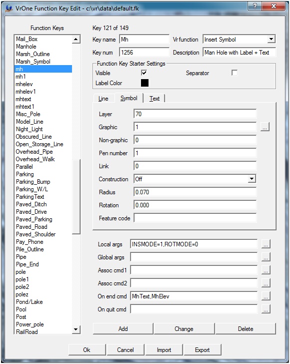
A Function key to place Man Hole symbols with a label and elevation
Generating a DTM Surface for Contours
Once points and break lines have been collected The DTM (Digital Terrain Modeling) application in VrOne or VrTwo may be used to to create contours. There are two applications available when generating DTMs. The Set DTM (SetDtm) application allows the configuration of the DTM parameters and the saving and recalling of these parameters. Once the DTM parameters are set then the Run DTM (RunDTM) command will generate the 3-dimensional surface and place contours and triangles if specified.
Other related application include Insert Line Text (InsLte) which is used to place labels on contours and Manage DTM Surfaces (ManDtm) which is an optional package that runs inside VrOne and VrTwo and compares DTM surfaces for volume calculations.
Configuring DTM With the Set DTM Command
To configure the DTM engine use the Set DTM (SetDtm) command or selected DTM->Set DTM parameters. See Set DTM for more information.
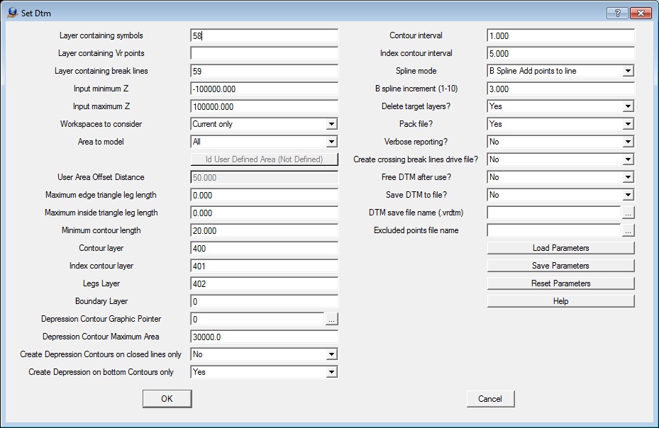
Set Dtm dialog box
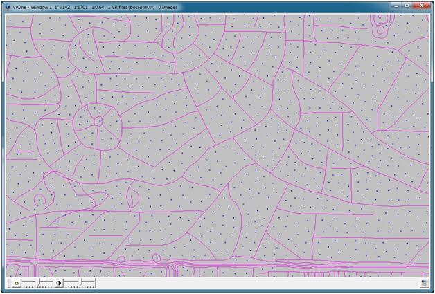
Graphics window showing points and break lines
Processing DTM With the RunDtm Command
Once settings have been configured for the DTM engine through the Set DTM (SetDtm) command, the DTM engine can be started from Run DTM (RunDtm) key-in or selecting DTM->Run DTM from the Main Window pull down menu.
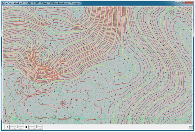
Graphics window showing points, break lines, triangles and contours
Draping Features to DTM Surface
The Drape application has the ability to drape lines, symbols and text over a active DTM surface. It is also possible to drape the active cursor location to the DTM surface to compute a real-time elevation of the cursor. To drape entities onto a DTM surface the following requirements must be met.
| 1. | Free DTM after use must be set to no in the Set DTM (SetDtm) parameters. |
| 2. | A DTM surface must be active by running Run DTM (RunDtm) at least one time. |
| 3. | The Z Source must be set to 'DTM surface if active' This can be set by the Z Source (ZSou) command or by selecting Input -> Z source from the Main Window. |
| 4. | Draping is performed by the Drape (Dra) application or by selecting DTM->Drape from the Main Window. |
See Drape (Dra) for more information about the this batch application.

The Drape dialog box
List of Commands
Please see the List of Commands document for to view the available commands and applications in VrOne and VrTwo.
Cleaning up Data
Once the vector data has been collected, there are several steps that can be performed in VrOne for clean up and preparation for final delivery. Although these steps can be performed in VrTwo, it is sometimes more convenient to perform them in VrOne. Clean up may involve trimming and extended lines to eliminate overlapping lines (overshoots) or gaps between lines (undershoots). Another common task is to take the data contained in each stereo model and rearrange it into final project sheets. This may involve merging models, joining lines, and cutting out into sheets.
Batch Trim (BatTri)
Batch Trim (BatTri) batch application may be used to trim lines and text. The batch application allows the user to collect data without having worry about line overshoots and undershoots. Typical uses for batch trim would include: Trimming Sidewalks to buildings , Contours to buildings , Sidewalks to driveways, Clearing contours through trees. Another application that works with the trimming and noding of lines is Batch Node (BatNod).
Batch Join (BatJoi)
The Batch Join (BatJoi) batch application join lines within parameters specified. Options include limiting the lines to be joined by Layer, Mode, Graphic Pointer, horizontal distance and elevation. This avoids joining entities such as fence lines to entities such as road edges. Many lines may be joined together as a single entity. This results in cleaner and more contiguous data base. Batch join has the ability to join lines into a single entity if they exist in the same workspace and the ability to match the lines if they reside in separate workspaces. There is also an option to match lines only in which the lines will be graphically joined but the lines will remain as separate entities in the data base. In this case the lines will retain their original line properties. When lines are joined into a single entity the properties from the first line will be used. Join Lines (JoiLin) is an interactive application in which the user chooses the lines to be joined.
Make Polygon (MakPol)
Make Polygon (MakPol) looks at the spatial relationship of existing line segments and creates enclosing polygons around areas containing centroid symbols. See the Make Polygon documentation for more details. A video tutorial of Make Polygons is available also.
Exporting Data
There are many options for export data from VrOne/VrTwo to other systems. Options include DXF (AutoCAD), Microstation, Shape File, ASCII (Text list), LAS (LiDAR) and DSFL. Many of these output formats have an input translator to translate data into VrOne/VrTwo.
Exporting to DXF
The DXF format is commonly used to translate map data to Autodesk’s AutoCAD program. Due to the popularity of the format, it is used by many other CAD and GIS (Geographic Information Systems) systems for the transfer of map vector data. From GIS to civil engineering systems, DXF is considered the de-facto standard for moving vector data. Experience has shown that DXF is also well suited to move vector data to the ARC INFO GIS system although a Shape File translator is available in VrOne and VrTwo. See DXF Out and DXF In for more information on the DXF translators.
Exporting to Microstation
VrOne translates files to and from Microstation using a neutral file. This allows both programs to read and write map data using their internal libraries. This results in a more flexible and accurate translation. See Microstation translators and Microstation Out (MstOut) and Microstation In (MstIn) for more information about these translators.
Exporting to Shape Files
The Shape File format is used by ArcView GIS software sold by ESRI Corporation. At the time of this writing, a free Shapefile viewer named ArcExplorer was available for download at the ESRI web site at the following Location. See Shape Out (ShaOut) and Shape In (ShaIn) for more information about these translators.
Exporting to ASCII files
The ASCII Out (AscOut) translator provides a flexible way to write out Vr vector data to simple ASCII list files. The data may be written out using space or comma-delimited format. The ASCII Out (AscOut) translator uses a line based format. Symbols and Text are translated one entity per line, and Lines are translated one vertex per line. This format is not suited for detailed mapping translations, but is useful for simple line work or control point exporting. See ASCII Out (AscOut) and ASCII In (AscIn) for more information about these translators.