Vr Mapping |
ON-LINE REFERENCE DOCUMENTATION CARDINAL SYSTEMS, LLC |
Vr Model Set (VrModSet)
Type: Stand-alone application (VrModSet.exe)
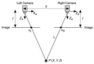
Stereo model diagram
Overview
There are two stand-alone programs for setting up 3D stereo models for the VrTwo soft copy environment: VrTwo Orientation and Vr Model Set (this program). Vr Model Set is a simplified redesign of VrTwo orientation. Aerial triangulation results from various software packages are imported directly. Vr Aerial triangulation project files are opened and edited without any conversion needed. The best best models to orient are selected based on simple user defined overlap parameters; this particularly useful for UAV work.
VrTwo Orientation (Vr2Ori) - Offers a more hands on approach to orientation with the option to import aerial triangulation measurements and the ability to set a model using the traditional three-step orientation method (interior, relative, absolute ordination). Please see VrTwo Orientation for more information about this program.
For best results, image orientations should be refined using aerial triangulation. The procedure for setting models from directly georeferenced image orientations is identical, but will have lower quality results. The work flow for the Vr Model Set program is the organization of the following inputs. The first three items are required.
| • | Camera Definitions - Camera definitions are represented by the parameters in the Vr Camera (.cam) files which include items such as focal length, principal point and distortion values. Cameras definitions affect the exterior orientations (EOs). If the focal length, principal point, or distortion values change there will be a shift in the EO values. To replicate the aerial triangulation (At) results, the cameras must be identically defined here as they were when AT was was done. |
| • | Images - Tif or jpeg image files (Vr Image Utility can be used to rapidly convert other formats). |
| • | Orientations - Interior (IO) and exterior (EO) orientations are required to set stereo models. Much like camera data, the interior orientations (IOs) need to be identical to the those used during AT process. This is automatic for digital images, and can be imported for film imagery in various formats. EOs may be in one of the supported EO formats. Measurement import is not supported (though that is still an option in Vr Two Orientation). |
| • | Control - Control, or "ground control", is useful for verifying that all the inputs are correct. If control data is provided, models will also have the ability to drive to the control points to check their residuals. |
If prior work was performed in the Vr Aerial Triangulation, VrTwo Orientation or Vr Image Utility program, these project files may be used in Vr Model Set. It is suggested that the project data be checked after import and that the EOs be re imported. This is because GPS or other approximate EOs are frequently imported in VrAirTrig and may need to be overwritten. This can be done in the "Orientations and Control" tab.
If there was no prior work done in VR a new project may be created. The new project command will prompt you to choose a file name and will then open the Edit Project window.
Command Reference
File
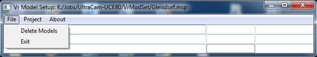
Vr Model Set File menu
Delete Models
This is a utility for deleting model(s). Models that are not setup for on-the-fly viewing consist of a group of related files, using this utility deletes all related files together. On-the-fly models are only a single file and are easily deleted using this or other means.
Exit
Exits the Vr Model Set program.
Project
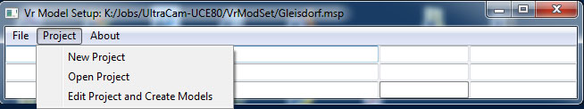
Vr Model Set Project menu
New Project
Creates a new project and prompts for a project file name and the Vr image file (.vim) file location.
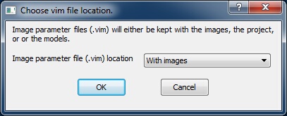
Choose vim file location dialog
Image parameter file (.vim) location - Each image that is used by Vr Mapping has a corresponding .vim file which is the same name as the image with with a .vim extension. The .vim file contains information about the image including strip and photo number information, pixel size, camera name, GPS time when the image was taken, interior orientation measurements, and exterior orientation parameters.
Options for the .vim file location include.
| • | With images - The .vim files will be in the same folder that contains the image. This is the recommended setting, there is less potential for confusion because all Vr Projects will reference the same vim file for each image. |
| • | Project folder - The .vim files will be in the project folder. The project folder is defined when the project is created when the project file name (.msp) was entered. |
| • | Model folder - The .vim files will be placed in the folder that is defined to store the resulting stereo model files. |
After the project has been created, program execution goes to Edit Project (see below).
Open Project
Opens an existing project. The project may be a Vr Model Set (.msp), Vr Aerial Triangulation (.atp), VrTwo Orientation (.vpr) or a Vr Image Utility (.iup) project.
After the project has been opened, program execution goes to Edit Project (see below)
Edit Project and Create Models
Edits an existing project and creates stereo models. There are four tabs or steps that make up the work flow of defining/editing parameters and creating stereo models. Edit Project is described below.
About
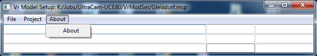
Vr Model Set About menu
About
Displays information about Vr Model Set including the version number and release date.
About dialog
Edit Project and Create Models
Cameras and Photos Tab
Camera definitions (.cam) files may be created, added, and (or) edited. Images are assigned to specific cameras.
Image rotations may also be defined. The image rotation tells the software if an image has been rotated from its raw state and allows the camera calibration and interior orientations to be correctly applied. It is strongly recommended that images remain in their original raw state (un-rotated) through the entire process from aerial triangulation to end project. Rotating images is an unnecessary step and doing so complicates the work flow and contributes to confusion and errors.
Add or create cameras to begin. Once a camera is defined, it can be selected in the camera table in order to assign it images (using the 'Assign photos to camera' button). This ensures that no image can be added to the project without knowing its camera. Double clicking on an camera to edit the parameters.
Selecting a camera in the left table will display the images assigned to it in the right table. Selecting images in the right table enables the 'Remove Photo(s)' and 'Set Rotation(s)' buttons--which will only operate on the selected images.
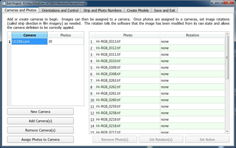
The Cameras and Photos tab in the Edit Project dialog
New Camera
Creates a new camera definition (.cam file). See Edit Camera for information on the entry/editing of camera parameters.
Add Camera(s)
Adds existing cameras to the project.
Remove Camera(s)
Removes cameras from the project. The cameras to be removed are highlighted in the left pane before pressing this button.
Assign Photos to Camera
Assigns a photo or group of photos to a camera definition. Select a camera from the left pane then press "Assign Photos to Camera".
Remove Photo(s)
Removes selected photos from the project. Select photo(s) in the right table to activate this button.
Set Rotation
Sets the rotation of photo(s) selected in the right pane. A dialog will be displayed which will allow a photo rotation of None, 90 degrees clockwise, 180 degrees or 270 degrees clockwise. These rotations refer to images that have been saved on the disk in rotated positions. Knowing that images have been rotated allows orientation and camera data to be correctly applied. Users are advised to never rotate images, it causes confusion and gains nothing.
Set Active
Images set to inactive are not used for creating models.
Orientations and Control Tab
On this tab, image orientations are imported and a control (ground) file may be defined. The table lists the name and the status of the interior and exterior orientations for each photo. If the interior and exterior orientations are defined for a photo, the number of control point that projects into the photo is shown in the rightmost column.
If the camera definition for a photo indicates that it is a digital camera then interior orientations are automatic. If the camera definition for a photo specifies a film camera with fiducials, the interior orientation measurements should be imported from the software that was used for aerial triangulation. If Vr Aerial Triangulation (VrAt) was used then this is done automatically when the project if first opened by this program.
Exterior orientations (EOs) must be imported. Supported EO input formats include Albany, Applanix , PATB transpose matrix, PATB, JFK, AeroSys, ISAT EO file, FotoG, BINGO, ISAT 'photo' file, MATCH-AT and Optech LYNX. Is is suggested that the EOs be re-imported during this step to ensure that final aerial triangulation results (not GPS or other initial values) are being used.
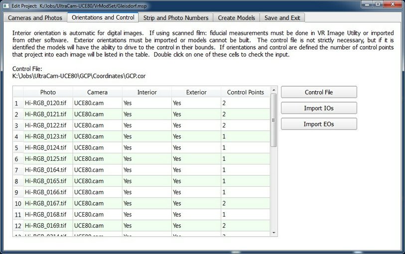
The Orientations and Control tab in the Edit Project dialog
Control File
Select a control (ground) file. Supported formats for control files in include the Vr Coordinate file (.cor), text file (.txt) or data file (.dat). Any file with the following format can be used:
PtName1 X1 Y1 Z1
PtName2 X2 Y2 Z2
...
Import IOs
Interior orientations may be imported from several formats including ISAT (photo), SOCET SET (.iop) or MATCH-AT (.prj)
Import EOs
Exterior orientations may be imported in various formats.
Double-click of Control Points Field
If the number of Control Points value for a photo is greater than zero, the cell may be double clicked to view photo thumbnails of a control point. If the number of control points is greater than one a dialog will allow the selection of which control point to view.
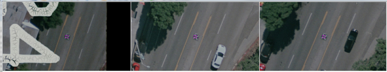
Photo thumbnails displaying the area around a control point
Strip and Photo Numbers Tab
The Strip and Photo Numbers tab allows the assignment of strip and photo numbers. Strip and photo numbers can make job organization and management easier. Although this capability exists for the convenience of project organization, it may be needed for importing some exterior orientation formats such as Aerosys, Albany, ISAT and JFK. Strip and photo numbers allow models to be named in a meaningful way that communicates the individual model's relation to the whole project. It is good practice to take the time to make sure they are assigned correctly.
For most jobs strip and photo, numbers will be calculated automatically based on the image EOs, or obtained from a VrAirTrig or Vr Two Orientation project when first opened in Vr Model Set. Strip and photo numbers that are calculated based on EOs will not match those in EO files or numbers imbedded in image names. In this case, the strip and photo numbers can be overwritten manually or derived from the photo names.
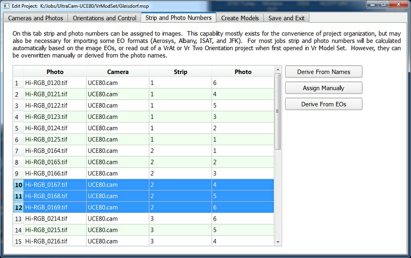
The Strip and Photo Numbers tab in the Edit Project dialog
Derive from Names
Derives the strip and photo numbers from the photo file names. The "Derive from Names" button operates on a group of selected photos and displays the following dialog.
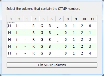
Select strip and photo number columns
In the above example the first five photo names are displayed (eg. Hi-RGB_1020.tif). Each character in the image names is separated into columns (1-11).
To assign the strip numbers, the columns that contain the strip numbers are highlighted by clicking or dragging on the column numbers and pressing the Ok button. In this example, the strip columns are 8 and 9, and the images are all assigned to strip 1.
Then, to assign the photo numbers, the columns that contain the photo numbers are highlighted by clicking or dragging on the column numbers and pressing the Ok button. In this example, the photo columns are 9, 10, and 11, and photos are numbered 120-124.
Assign Manually
Manually assign a group of photos to be a strip. Within the selected group the photo numbers will be assigned in alphabetical order starting at photo number 1.
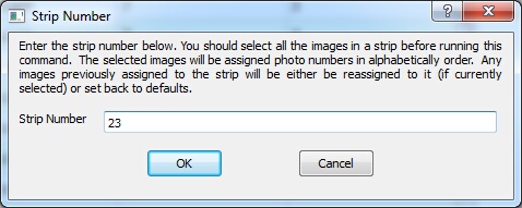
Assign strip numbers manually dialog
Derive from EOs
Obtains the strip and photo numbers from the current exterior orientation file.
Create Models Tab
Once the parameters are entered on the previous tabs, models are created on the Create Models tab.
With some of the new digital camera platforms such as the UltraCam and UAV (drone) imagery, it's possible to obtain a large amount of photos for a job. The Create Models process allows the user to select the desired model overlaps to optimize coverage with the minimal amount of models. It's also possible to set 60% overlapped photos on projects that have 80% or greater photo overlaps to maximize the base to height ratio of the resulting stereo models.
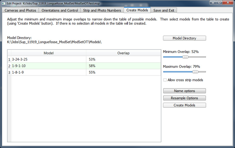
The Create Models tab in the Edit Project dialog
Model Directory
Define the directory (folder) to place the resulting stereo models.
Minimum Overlap
The minimum overlap slider is used to set the lower bounds of the stereo model overlap. The lowest recommended setting is 50%, setting it lower will frequently result in lack of coverage.
Minimum Overlap
The maximum overlap slider is used to set the upper bounds of the stereo model overlap. This parameter must be greater than the Minimum Overlap.
Allow cross strip models
If checked cross strip models with applicable overlaps will also be created.
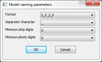
Name options
Interface to model naming options. After closing the dialog the 'Model' column in the table will update with the new names.
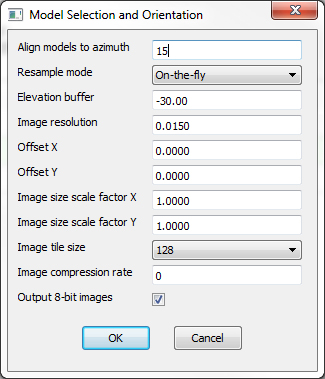
Resample Options
Begins the model creation process, by prompting for resampling parameters.
Model resampling parameters |
Align models to azimuth This parameter is a north azimuth in degrees, and should be set to approximately perpendicular to the flight lines. There are two ways to view a 3D stereo model. The two ways have opposite image Y axis directions. The models will be set to make the Y image axis as close as possible to this azimuth. The choice is binary and alignment, therefore, can not be perfect. However, it does prevent unnecessary 180° perspective flipping. Resample mode Images can be resampled using the nearest neighbor, bilinear, bicubic, or on-the-fly algorithms. On-the-fly is recommended because it is the fastest and simplest. On-the-fly models are also the easiest to pass around. Elevation buffer The elevation buffer is a percent of the flying height. The larger the number, the larger the area that will be sampled. If models seem too small, try using a great value here. Typical ranges are 0-20%. The default is 2%. Image resolution This parameter defaults to maintaining the image native resolution. It is the pixel size of the output image in millimeters. It allows users to super or sub-sample the images, but this is not recommended. Offset X This parameter shifts the area of the model that is resampled in the x direction. It is not usually necessary to adjust this parameter. Offset Y This parameter shifts the area of the model that is resampled in the y direction. It is not usually necessary to adjust this parameter. Image size scale factor X This parameter scales the area of the model that is resampled in the x direction. It is not usually necessary to adjust this parameter. Image size scale factor Y This parameter scales the area of the model that is resampled in the y direction. It is not usually necessary to adjust this parameter. Image compression rate Output images can be compressed, but it is not recommended. Output-8-bit images If checked resampled images will be 8-bit regardless of the bit depth of the input images.
|
Create Models
Starts the model creation. Users may be prompted to delete models already in the output directory.
Save and Exit
Saves the currently defined parameters and exits the "Edit Parameters and Create Models dialog" and returns to the main menu.