Vr Mapping |
ON-LINE REFERENCE DOCUMENTATION CARDINAL SYSTEMS, LLC |
Getting Started With VrOne

VrPoint (LiDAR / Point Cloud) Entity
“Get the job, do it right, get it out on time, make a profit. That’s what every mapping company is about!”
- Jeff Crenshaw
Northern Division Manager
North American Mapping
VrOne is a powerful photogrammetric vector collection and editing package with image display capability. Photogrammetry today requires the mapping professional to deliver vector, image and digital terrain model (DTM) data as digital products. VrOne addresses many of the problems encountered in handling the collection, editing, and plotting of vector, image, and DTM data. Map updating and revision may also be performed with VrOne.
Features
| • | Up to 2000 vector files may be open |
| • | Up to 2000 image files may be open |
| • | Up to 8 windows may by open |
| • | Runs on Windows XP and Windows 7 |
| • | 32-bit and 64-bit versions are available (64-bit is available in versions 5.1 and above) |
| • | Supports application overlaying (see below) |
| • | Supports run-time key-ins |
| • | Time tested fast vector access and display |
| • | Fast image read and display |
| • | Supports user-defined symbols and line fonts |
| • | Rich, pragmatic set of mapping applications and batch routines |
Input sources
| • | Analog photogrammetric instruments |
| • | Analytical photogrammetric instruments |
| • | Stereo softcopy |
| • | XY digitizing tablets |
| • | Mouse |
| • | Various file formats |
Vector database
| • | Designed for mapping and photogrammetry |
| • | 3D double precision |
| • | 32,001 data layers |
| • | Unlimited file size |
| • | Unlimited number of points on a line |
| • | LiDAR (VrPoint) storage capability |
| • | 48 character feature code available for each entity (except VrPoint) |
| • | 32 bit non-graphic pointer |
| • | Text labels up to 512 characters |
| • | Support for 256 vector colors |
Image handling
| • | Support for standard TIFF files with world file and other image formats |
| • | Uses image pyramids |
| • | Color (24 bit) and Grayscale (8 bit) and other image depth support |
| • | Images can be displayed and plotted at any scale |
Digital Terrain Modeling (DTM)
| • | Embedded in VrOne |
| • | Uses points and break-lines currently in file |
| • | Adds contour and triangles into file |
| • | Models entire file(s) or current view window |
| • | Option to keep DTM surfaces on-line for cursor and entity draping |
Plot Formats
| • | Ability to plot to system printers and plotters |
| • | HPGL for vectors to old HP line plotters |
| • | HPGL/2 for vectors to current HP plotters |
| • | HPGL/2 RTL for vectors and Grayscale/Color images to current HP plotters |
| • | PostScript for vectors and Grayscale/Color images to various systems |
“Rule of thumb; if you think something is clever and sophisticated, beware – it is probably self indulgence.”
- Donald A. Norman, 1990
VrOne can be downloaded from the VrOne web page. Go to the home page, press the Download button, enter your username and password, and navigate to the desired folder.
There are two forms of VrOne installation:
| • | Full - VrOne full installation where all programs are installed. This is used for a new installation and most major revisions. |
| • | Patch – Used when only a few programs need to be updated. |
Full Installation
The full installation is always done from an executable program. This program may be downloaded from the VrOne web page or may be delivered via CD.
The name of the executable is as follows:
vr-MA_MI_BU.exe
Where:
MA - Major version number
MI - Minor version number
BU - Build number
Example:
vr-05_01_05.exe would be Vr Mapping version 05.01.05
Once the file has been downloaded, run this program and follow the prompts to complete installation.
Patch Installation
Patch installations are partial installations designed to update certain programs and/or data. A full installation must be completed before patches can be applied. Patches are downloaded and installed in the same manner as full installations.
VrOne Folder Structure
Following is the default VrOne folder structure:
C:\vr
The VrOne base folder. It may be necessary to place VrOne on another drive such as D: or E:. If possible, the default folder of vr should be used.
C:\vr\bin
VrOne executables folder. Contains all Vr Mapping Software programs.
C:\vr\data
Contains VrOne data files, such as:
| • | VrOne character sets used to draw text into the graphics windows |
| • | The default symbol library (default.sym) |
| • | The default screen color table (defaultscreen.ct) |
| • | The default plotter color table (defaultplotter.ct) |
| • | The default pen table (default.pen) |
| • | The default Function Key file (default.fk) |
| • | The default Macro file (default.mac) |
| • | The default Menu Board definition file (default.mb) |
| • | The default key pad definition file (default.kp) |
| • | The SOCET SET VrOne mouse button definition file (vrone.acc) |
| • | VrOne file containing the digitizing table menu board overlay (menuboard.VR) |
| • | VrOne file containing the Polytel Keyport 300 key overlay (kp300.VR) |
| • | VrOne file containing the Cedeq Enterpad P120 key overlay (cedeq.VR) |
| • | Download key assignments for the Cedeq key pad (vrone.pos) |
| • | Various .bmp images used by VrOne during runtime. |
NOTE: These files are re-installed each full installation. However, if these files are modified, it is recommended they be moved to another folder or renamed.
C:\vr\hostdir
Contains run-time parameter files. It is delivered empty. Parameter files are created as needed by VrOne.
Running VrOne
After installation, links to the Vr Mapping programs are placed in a folder called Vr Mapping and this folder is placed on the desktop. VrOne can be run by double clicking the VrOne icon or by typing vrone from a command prompt window.
Release Notes
Each full installation of VrOne will have a corresponding Release Notes file that will document recent changes and additions to VrOne and it’s support files and programs.
“Nothing is happening, there are no lights and everything is quiet… Oops, it’s unplugged.”
- A hardware support call, 1981
Before starting VrOne for the first time, the VrOne configuration program should be run to set the proper input devices and parameter files. This is not a requirement and the configuration defaults allow VrOne to start the first time.
VrOne will start by opening the Main Window and one Graphics Window.
VrOne's main and graphics windows
If the current input device is the mouse, moving the mouse across the Graphics Window should show a cursor. The coordinates in the main window should change. Pulling down the File menu and selecting "Open Vr File" will open a VrOne file.
Starting an Application (Command)
Select an item from a dropdown menu to start commands. Alternatively, commands may be started from a key-in using the command name. Each command name is the first three letters of the first two words on the pull down. For example: The command name for Insert line is InsLin. If this rule is not followed the key-in is listed after the command in parentheses. For example: Zoom all (zooa).
The Main Window
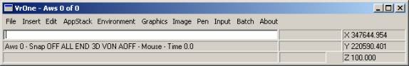
VrOne's main window
The Main Window in VrOne contains the command pull down menus, a key-in area, two information areas, the application (command) stack, a progress bar, and the coordinate display.
Command names may be typed into the key-in area at almost any time. The mouse must be in the Main or Graphics window for keystrokes to be entered in the key-in area.
The active workspace and the number of currently opened workspaces is shown on the border of the Main Window.
The Graphics Window
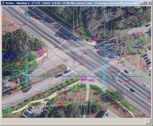
VrOne's graphics window
The VrOne graphics window displays vectors and images. In Windows XP and Windows 7 there may be up to 8 windows open at a time. At the top of the window is displayed the window number, the scale of the window, the number of VrOne files opened and the number of images open. Also displayed is the image pyramid scale (i.e. 1:3.10) and the first two image names.
In the lower right corner of the graphics window is a push button that allows setting display of images, image names and image edges.
The Menu Keys Dialog
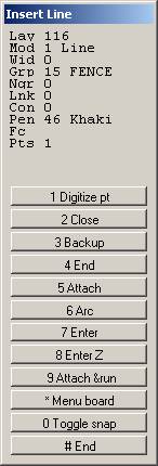
The Menu Keys Dialog window is displayed by most interactive commands. At the top of the window is the command name. The next area displays the entity parameters. This information is command dependent and normally shows where the data is to be stored on insert commands or where the data came from on edit commands.
The third area is the menu keys area. These show what functions are assigned to the 12 menu key buttons. These keys are normally mapped onto an input device such as the keypad on a digitizing tablet cursor. They are also mapped onto the 12 function keys on a standard keyboard.
Commands
| • | Local Commands – These commands are passed to the current application (command) and are often used to modify parameters of that command. For example, if Insert Line is the current application and LAY=23 is keyed in then the current layer for Insert Line would be changed to 23. |
| • | Global Commands – These commands operate on VrOne globally. For example if SnaOn (Snap on) is keyed in then snap is turned on for all active commands. Global commands include application (command) names also such as InsLin (Insert Line). |
“Everything should be as simple as possible...
But no simpler.”
- Albert Einstein
VrOne is a mapping system. It is normally used as the first step in map data collection. Although it may be used to edit vector data and generate DTM, the VrOne database will normally be translated to another system for final processing. These other systems include ARC-INFO, AutoCAD, and MicroStation.
It is important that the original database is simple enough to make moving the data easy. The VrOne database is an entity-based non-topological structure. Although the database contains some non-graphic and extended information other CADD systems do not, it cannot be considered a true Geographic Information System (GIS). It can however, prepare vector data for accurate translation to GIS and other CADD systems.
The VrOne database is a single file with all vector information contained in the one file. Support files include the symbol library and pen table (if specified). The size of the file is operating system dependent.
NOTE: The VrOne database is considered proprietary information to Cardinal Systems, LLC and is here for informational purposes for Vr Mapping uses. Copyright © 2000-2011 by Cardinal Systems, LLC.
Each VrOne entity contains the following information:
Layering is a method of logically grouping graphic data. Buildings, roads and trees will probably occupy different layers.
Range: 1 to10,001
Mode
Defines the entity type as follows:
1 |
Line |
2 |
Splined Line |
3 |
Symbol |
4 |
Text |
5 |
Point (LiDAR) |
Arcs in VrOne are embedded in a line and contain arc flags to identify the start, mid-point, and end of each arc.
Range: 1 to 5
Graphic Pointer
The graphic pointer represents the display characteristics of an entity. A line will have a graphic pointer that might define it as a fence, tree or water line. A symbol will have a graphic pointer that might define it as a circle, cross or highway symbol.
Range: 1 to 1000
Non-graphic Pointer
May be used to define a pointer to non-graphic data. Currently unimplemented, although it can be set by the user.
Range: -2 billion to 2 billion
Pen Number
Defines the color of the entity.
Range: 1 to 256
Link
Currently unimplemented, although it can be set by the user. In the future, it can link entities together or represent entity ownership. For example: This sidewalk and fence belong to this house.
Range: -2 billion to 2 billion
Construction Flag
Line entities may be flagged as construction, which allows them to be turned off. This line description might be applied to hidden lines, reference lines, or other non-topological lines.
Range: 0 to 1
Feature Code
A user-defined 48-character non-graphic alphanumeric field for further entity classification.
Range: 48 characters
All lines in VrOne are three-dimensional. The number of points per line is unlimited (within the range of physical memory in the computer). Each line contains an entity header and the following information for each line point.
X Y Z
Each line point is represented by a double precision, three-dimensional coordinate.
Range: -1.8e307 to 1.8e307
Width
Represents the width of the line. This number defines the number of line strokes to place on each side of the centerline. The distance between the strokes is user-defined.
Range: 1 to 256
Pen Code
Defines the pen up/down status to the current point as follows:
| • | 1 - Up |
| • | 2 - Continue |
| • | 4 - End |
This allows a line to appear broken graphically but remain contiguous in the VrOne database.
Range: 1 to 4
Arc Flag
Defines the arc status of the current point as follows:
| • | 1 - Beginning or end of arc. May also be used to define point of reverse curve (PRC). |
| • | 2 - Mid point on the arc |
| • | 3 - Point on the arc |
Range: 1 to 3
Code
Commonly used to define cross section codes such as top of bank, bottom of bank and edge of road. Cross sectioning has been largely replaced by DTM over the last several years and VrOne does not support cross sectioning.
Range: 0 to 255
Flag
System defined bit encoded flags. This field is not user definable.
Range: 0 to 255
Each symbol entity contains an entity header and the following information:
X Y Z
Double precision three-dimensional coordinate.
Range: -1.8e307 to 1.8e307
Radius
Symbol radius in ground units.
Range: -1.8e307 to 1.8e307
Rotation
Symbol rotation expressed counterclockwise from the X-axis in decimal radians.
Range: 0 – 2 * p. This value will be entered and displayed by VrOne as decimal degrees with a range of 0 to 360.
Each text entity in VrOne may contain up to 512 characters. Each text entity contains an entity header and the following information:
X Y Z
Double precision three-dimensional coordinate.
Range: -1.8e307 to 1.8e307
Justification X
Text justification along the X-axis
| • | 1 – Left |
| • | 2 – Center |
| • | 3 – Right |
| • | 4 – Decimal |
Range: 1 to 4
Justification Y
Text justification along the Y-axis
| • | 1 – Lower |
| • | 2 – Center |
| • | 3 – Upper |
Range: 1 to 3
Font Number
Text font to be used when drawing text.
1 |
CI |
Complex Italic |
2 |
CR |
Complex Roman |
3 |
CS |
Complex Script |
4 |
DR |
Duplex Roman |
5 |
GE |
Gothic English |
6 |
GG |
Gothic German |
7 |
GI |
Gothic Italic |
8 |
HS |
Standard |
9 |
SR |
Simplex Roman |
10 |
SS |
Simplex Script |
11 |
TI |
Triplex Italic |
12 |
TR |
Triplex Roman |
Height
Text height in ground units.
Range: -1.8e307 to 1.8e307
Width
Width of one text character in ground units.
Range: -1.8e307 to 1.8e307
Rotation
Text rotation expressed counterclockwise from the X-axis in decimal radians.
Range: 0 – 2 * π. This value will be entered and displayed by VrOne as decimal degrees with a range of 0 to 360.
Slant
Text slant.
Example: This text is slanted
Range: 0 – π. This value will be entered and displayed by VrOne as decimal degrees with a range of 0 to 180.
VrPoint (LiDAR / DSM / point cloud) Entity Information
Each VrPoint entity in the VrOne database contains XYZ coordinates and up to 16 attributes per point . The definition of point attribute data is dependent on the input system and format. Even though available in the Vr Mapping database, all attributes may not be defined in the LiDAR data input. The Vr Point structure is based on the ASPRS LAS Specification Version 1.2 and ASPRS LAS Specification Version 1.4. Please see LAS In or LAS Out or LAS 1.2 and LAS 1.4 for more information about the LAS format and Vr Mapping's implementation.
Each point entity contains an entity header and the following information:
X Y Z
Double precision three-dimensional coordinate.
Range: -1.8e307 to 1.8e307
Layer
Vr Layer number. This attribute is not defined in the LAS specification.
Range: 0-30001
Intensity
The intensity value is the integer representation of the pulse return magnitude. This value is optional and system specific.
Range: 0-65535
Display Flag
Flag to indicate if the point should be displayed. This attribute is not defined in the LAS specification.
Range: 0=No 1=Yes
Return Number
The Return Number is the pulse return number for a given output pulse. A given output laser pulse can have many returns, and they must be marked in sequence of return. The first return will have a Return Number of one, the second a Return Number of two, and so on up to five returns.
LAS 1.2 - Range: 1-5
LAS 1.4 - Range: 1-15
Number of Returns
The Number of Returns is the total number of returns for a given pulse. For example, a laser data point may be return two (Return Number) within a total number of five returns.
LAS 1.2 - Range: 1-5
LAS 1.4 - Range: 1-15
Scan Direction
The Scan Direction Flag denotes the direction at which the scanner mirror was traveling at the time of the output pulse. A bit value of 1 is a positive scan direction, and a bit value of 0 is a negative scan direction (where positive scan direction is a scan moving from the left side of the in-track direction to the right side and negative the opposite).
Range: 0-1
Edge Flag
The Edge of Flight Line data bit has a value of 1 only when the point is at the end of a scan. It is the last point on a given scan line before it changes direction.
Range: 0-1, 1=Point is edge of flight line
Classification
Point Classification. If a point has never been classified, this value must be set to zero.
LAS 1.2 - Range: 0-31
0 |
Created, never classified |
1 |
Unclassified |
2 |
Ground |
3 |
Low Vegetation |
4 |
Medium Vegetation |
5 |
High Vegetation |
6 |
Building |
7 |
Low Point (noise) |
8 |
Model Key-point (mass point) |
9 |
Water |
10 |
Reserved for ASPRS Definition |
11 |
Reserved for ASPRS Definition |
12 |
Overlap Points |
13-31 |
Reserved for ASPRS Definition |
LAS 1.4 - Range: 0-255
0 |
Created, never classified |
1 |
Unclassified |
2 |
Ground |
3 |
Low Vegetation |
4 |
Medium Vegetation |
5 |
High Vegetation |
6 |
Building |
7 |
Low Point (noise) |
8 |
Reserved |
9 |
Water |
10 |
Rail |
11 |
Road Surface |
12 |
Reserved |
13 |
Wire - Guard (Shield) |
14 |
Wire - Conductor (Phase) |
15 |
Transmission Tower |
16 |
Wire-structure Connector (e.g Insulator) |
17 |
Bridge Deck |
18 |
High Noise |
19-63 |
Reserved |
64-255 |
User defined |
Synthetic Flag
If set to 1, then this point was created by a technique other than LiDAR collection such as digitized from a photogrammetric stereo model.
Range: 0-1
Key Point Flag
If set to 1, this point is considered to be a model key-point and thus generally should not be withheld in a thinning algorithm.
Range: 0-1
Delete Flag
If set to 1, this point should not be included in processing (synonymous with Withheld).
Range: 0-1
Overlap
If set, this point is within the overlap region of two or more swaths or takes.
LAS 1.2 - Not defined
LAS 1.4 - Range: 0-1
Scan Angle
LAS 1.2 - The Scan Angle has a valid range from -90 to +90 and is the angle (rounded to the nearest integer in the absolute value sense) at which the laser point was output from the laser system including the roll of the aircraft. The scan angle is within 1 degree of accuracy from +90 to –90 degrees. The scan angle is an angle based on 0 degrees being nadir, and –90 degrees to the left side of the aircraft in the direction of flight.
Range: +90 to -90
LAS 1.4: The Scan Angle is a value that represents the rotational position of the emitted laser pulse which respect to the coordinate system of the data. Down in the data coordinate system is the zero position. Each increment represents 0.006 degrees. Counterclockwise rotation, as viewed from the rear of the sensor, facing in the along-track (positive trajectory) direction, is positive. The maximum value in the positive sense is 30,000 (180 degrees)
Range: -32000 to 32000
Flight Number
User-defined flight numbed. This attribute is not defined in the LAS specification.
Range: 0-255
Point Source ID
This value indicates the file from which this point originated. Valid values for this field are 1 to 65,535 inclusive with zero being used for a special case discussed below. The numerical value corresponds to the File Source ID from which this point originated. Zero is reserved as a convenience to system implementers. A Point Source ID of zero implies that this point originated in this file. This implies that processing software should set the Point Source ID equal to the File Source ID of the file containing this point at some time during processing.
Range: 0-65535
Sensor (Scanner Channel)
The Scanner Channel is used to indicate the channel, or scanner head of a multi-channel system. Channel 0 is used for single channel systems.
LAS 1.2: Not defined
LAS 1.4: Range 0-3
NIR
Near Infrared Channel. This attribute is available in VrPoint (LAS) format 8.
LAS 1.2: Not defined
LAS 1.4: 0-65535
GPS Time
GPS time at which the point was acquired in seconds. This attribute is available in VrPoint (LAS) formats 1, 3, 6, 7, and 8.
Range: -1.8e307 to 1.8e307
Red
The Red image channel value associated with this point. This attribute is available in VrPoint (LAS) formats 2, 3, 7, and 8.
LAS Range: 0-65535
Vr Range: 0-255
Green
The Green image channel value associated with this point. This attribute is available in VrPoint (LAS) formats 2, 3, 7, and 8.
LAS Range: 0-65535
Vr Range: 0-255
Blue
The Blue image channel value associated with this point. This attribute is available in VrPoint (LAS) formats 2, 3, 7, and 8.
LAS Range: 0-65535
Vr Range: 0-255
For more information on the supported LAS formats please see:
Overview of Changes in 1.4 from 1.2
Following is an overview of the changes from LAS 1.2 to LAS 1.4. This list does not include all the differences. Please see the LAS format specifications for more details.
| • | The number of returns per LiDAR pulse and the return number has been extended from 5 to 15. |
| • | The sensor number is now included in version 1.4 and has a range from 0 to 3. |
| • | The overlap flag has been added. |
| • | The number of point classifications has been extended from 32 to 256. |
| • | The Near Infrared Channel (NIR) field has been added. |
| • | The scan angle is now defined with a range of -30,000 to 30,000 with a resolution of 0.006 degrees. |
Supported Point Data Records
LAS 1.4 supports waveform data, however the Vr Mapping LAS translators does not support this data so the LAS Point Data Record formats 4, 5, 9 and 10 are not supported. LAS 1.4 consists of 11 Point Data Record formats. Formats 0-3 are legacy formats from version 1.2 which are still supported and formats 6-8 are defined in the 1.4 specification. For more details on each of the supported point formats, please see the LAS format specifications in the LAS documentation listed above. Following are the record formats supported by Vr Mapping.
| • | Format 0 (LAS 1.2) - X, Y, Z, Intensity, Return Number, Number of Returns, Scan Direction Flag, Edge of Flight Flag, Classification, Scan Angle Rank, User Data, Point Source ID |
| • | Format 1 (LAS 1.2) - X, Y, Z, Intensity, Return Number, Number of Returns, Scan Direction Flag, Edge of Flight Flag, Classification, Scan Angle Rank, User Data, Point Source ID, GPS Time |
| • | Format 2 (LAS 1.2) - X, Y, Z, Intensity, Return Number, Number of Returns, Scan Direction Flag, Edge of Flight Flag, Classification, Scan Angle Rank, User Data, Point Source ID, Red, Green, Blue |
| • | Format 3 (LAS 1.2) - X, Y, Z, Intensity, Return Number, Number of Returns, Scan Direction Flag, Edge of Flight Flag, Classification, Scan Angle Rank, User Data, Point Source ID, GPS Time, Red, Green, Blue |
| • | Format 6 (LAS 1.4) - X, Y, Z, Intensity, Return Number, Number of Returns, Scan Direction Flag, Edge of Flight Flag, Classification, Scan Angle Rank, User Data, Point Source ID, Overlap flag, Sensor number, GPS Time |
| • | Format 7 (LAS 1.4) - X, Y, Z, Intensity, Return Number, Number of Returns, Scan Direction Flag, Edge of Flight Flag, Classification, Scan Angle Rank, User Data, Point Source ID, Overlap flag, Sensor number,GPS Time, Red, Green, Blue |
| • | Format 8 (LAS 1.4) - X, Y, Z, Intensity, Return Number, Number of Returns, Scan Direction Flag, Edge of Flight Flag, Classification, Scan Angle Rank, User Data, Point Source ID, Overlap flag, Sensor number,GPS Time, Red, Green, Blue, Near Infrared Channel (NIR) |
Additions and Modifications to the LAS Specification
| • | Vr Mapping contains a layer number for each point (1-32001) |
| • | Vr Mapping contains a flight number for each point (0-255) |
| • | Vr Mapping contains a display flag for each point (0-1) |
| • | The red, green, and blue values in LAS point data record formats 2, 3, 7, and 8 are defined with a range of 0-65535 (6 bytes). Vr Mapping scales these values to 0-255 (3 bytes) |
| • | LAS version 1.4 waveform data is not supported so LAS Point Data Record formats 4, 5, 9 and 10 are not supported. |
| • | LAS version 1.4 specifies the maximum number of points in an LAS file to be up to18 quintillion (18,446,744,073,709,551,615). Currently, Vr Mapping supports the LAS 1.2 specification which allows point counts up to 4 billion (4,294,967,295). |
“Hay don’t you remember, you called me Al…”
- Song from the depression era
VrOne commands are the heart of the system. While these commands are available from the pull-down menus in VrOne they are also available as key-ins. Key-in commands may be entered real-time or may be placed in macros and placed in function keys. See List of Commands for a list of the VrOne commands.
“The art of mapping is the art of organizing complexity.”
- Anonymous
Function Keys are the most important aspect of VrOne data collection. Taking the time to properly set up function keys before a project has started will save hundreds of hours of production time.
Function keys are the means of giving Vr Mapping (which internally is structured like a CADD system) a mapping system interface. This simplifies operations for mapping professionals by reducing the apparent complexity. For example, instead of using the CADD operation Insert Line (InsLin) to place a road, the operator could use a Function Key such as “Paved Road” which will assign the user definable parameters, attributes and behavior to Insert Line and start it. Function Keys are fully customizable, and-if the need arises-the full flexibility of the CADD operations is always available.
In practice, the mapping professional simply chooses the feature they want to collect and starts collecting data.
Entering its name or function key number may start a Function Key. These names or numbers may be keyed-in, placed in macros or even placed in other function keys.
The name of the Function Key file to use must be set in the VrOne configuration program (VrCfig). It is possible to have multiple function key files but only one can be active at a time.
Creating and Editing Function Keys
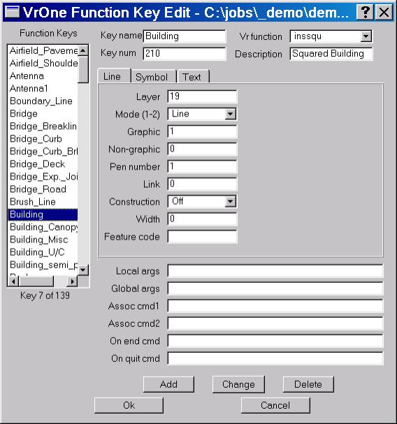
The Edit Function Key (EdiFun) dialog box
In the above dialog box a function key called Building is being created. The line that is placed by this function key will be a squared, un-fonted white line placed in layer 19.
Function Keys
Lists the currently defined function keys. A key may be selected and its parameters will be displayed to the right.
Key name
This is the name of the function key and may be used to start the function key. This name may be keyed in, placed in a macro or on another function key.
Key num
Function keys may also be numbered. This number may be entered to start the function key. This is useful when a menu board is not available and function keys must be started from the system keyboard.
Vr function
Defines the VrOne application to start when the key is executed. The proper Line, Symbol or Text tab will be selected depending on the type of VrOne command selected.
Desc
This is the function key description and is for information only.
Line Tab
Line parameters that will be assigned when the function key is executed.
Symbol Tab
Symbol parameters that will be assigned when the function key is executed.
Text Tab
Text parameters that will be assigned when the function key is executed.
Local Arguments
These commands will be executed when the function key is started. Normally local commands are placed here. For example, if the Insert Symbol command is started by a key and the symbol rotation needs to be turned on then ROTMODE=1 would be entered on the Arguments line. Multiple commands may be entered separated by a comma.
Global Arguments
These commands will be executed when the function key is started and when the function key is woken up after being overlaid. Normally global commands are place here. (See the On End Example)
For example, consider the state of a global command such as snap:
| • | Contour is started and it sets snap to end point (SnaEnd). |
| • | Drive overlays Contour and sets snap to intersect (SnaInt). |
| • | Drive is terminated and Contour wakes up and becomes active. |
| • | Since snap is global, the state is snap is now intersect. This is a state that Contour did not intend. |
Placing SnaEnd in the Wake up command of Contour ensures the state of this global parameter is what is expected.
Assoc cmd
Associate commands allow function keys to be linked. In many cases there may be several function keys used to insert a certain map feature. One might put in a line and another may put in text.
For example, consider the operation of inserting a parking area. This feature consists of line that will define the parking edge and a text label of “Parking Area”. There are two function keys defined which are ParkLine and ParkText. The associate command 1 of ParkLine has be set to ParkText as follows:
Assoc cmd1 |
ParkText |
| • | ParkLine is started and the parking lot edge is collected. |
| • | Ac1 is keyed in and the ParkText starts and “Parking Area” is labeled. |
| • | ParkText is terminated and ParkLine continues collecting the parking lot edge. |
On end cmd
The on end command allows one function key to execute a key-in, a macro or another function key each time an entity is saved. (See the On End Example)
For example, consider a spot elevation. This feature consists of a symbol and a text label. There are two function keys defined as follows:
SpotX Places the spot elevation X.
SpotElev Places the elevation of the previously read symbol.
The On end command of SpotElev is set as follows:
On end cmd |
SpotText |
When the spot elevation symbol is placed, the On End command will start Spot Text.
The On end command of SpotText is set as follows:
On end cmd |
Pop |
The Pop command tells VrOne to terminate the current application (command) that is at the top of the application stack.
| • | SpotElev is started and the spot elevation location is digitized. |
| • | SpotText starts automatically and the elevation of the first point is labeled. |
| • | SpotText terminates due to the On end Pop statement |
| • | SpotElev wakes up and the next spot elevation is ready to be read. |
There are more parameters that would need to be set to make the spot elevation functions keys work as expected but the above example shows how to chain function keys together.
On quit cmd
The on quit command will be executed when the function key application ends. This field may consist of key-ins, macros or other function keys. On quit commands are commonly used to set global parameters to a know state when an application ends. For example, if a function key was snapping to existing entities to obtain elevations, the on quit command may be used to turn snapping off.
“Become proficient in another language – or at least get the tapes and try.”
- Richard A. Moran
Macros give the ability to execute a group of VrOne commands as a single word. Macros can execute VrOne commands, function keys and other macros.
It is common to use macros to condition snap parameters; they is useful for turning groups of layers on and off.
In the following example, a macro called “R” toggles stereo roaming with the Toggle Roaming (TogRoa) command.
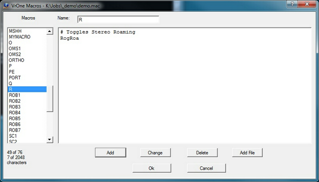
The Edit Macro dialog box
It is possible to have a macro start an application (command) such as Insert Line and then condition the local parameters, but Function Keys were designed to do this.