Vr Mapping |
ON-LINE REFERENCE DOCUMENTATION CARDINAL SYSTEMS, LLC |
Vr Configuration

Type: Stand-alone program (vrcfig.exe)
Detailed Description
Vr Configuration is a stand-alone program to set and edit program parameters for all Vr Mapping programs. The Vr Configuration program can be accessed from the \vr\bin folder. The executable name is vrcfig.exe. Alternately, Vr Configuration can be started from Windows Start -> VrOne -> VrConfiguration.
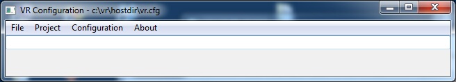
Vr Configuration Main Window
|
|||
|
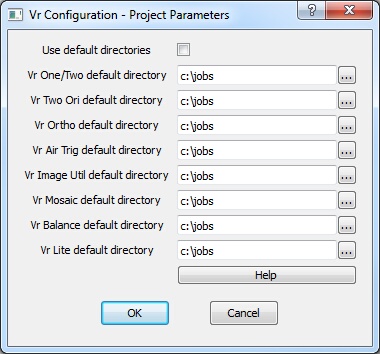
Project Parameters dialog
Sets the default directories for new files opened in Vr Mapping Software programs.
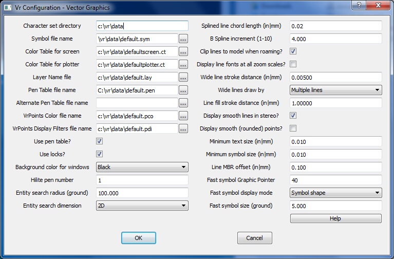
Vector Graphics dialog
Defines the directory where the thirteen VrOne character set files reside. The default character sets are: Ci, Cr, Cs, Dr, Ge, Gg, Gi, Hs, In, Sr, Ss, Ti, Tr The drive letter and path must be included in the file name.
Default: c:\vr\data
Symbol file name
Defines file name for the VrOne symbol file, which contains symbol and line font definitions. These are used to draw symbols and font lines when displaying a map. The drive letter and path must be included in the file name.
Default: c:\vr\data\symbols.sym
Color table for screen
Defines the file name for the color table, which cross-references VrOne Pen Numbers with colors. This is a text file and may be edited. The default Screen and Plotter color tables are the same but for Pen number 1, which is white for the screen and black for the plotter. The drive letter and path must be included in the file name.
Default: c:\vr\data\defaultscreen.ct
Color table for plotter
Defines the file name for the plotter table, which is used when drawing to a hard copy plotter from VrOne. The default Screen and Plotter color tables are the same but for Pen number 1, which is white for the screen and black for the plotter. The drive letter and path must be included in the file name.
Default: c:\vr\data\defaultplotter.ct
Defines the file name for the layer name file, which cross-references VrOne layer numbers with a layer name. The layer name is used for display purposes in VrOne and is used for the default layer names in DXF Out. The Layer Name file is a text file and may be edited with any text editor. The drive letter and path must be included in the file name.
Default: c:\vr\data\default.lay
Pen Table file name
Defines the file name for the pen table, which allows assignment of pen numbers to layers and modes. These pen numbers represent graphic screen colors or pen numbers on a line plotter. Each of the four modes in every layer can be given a separate pen number. Pen table use is optional in VrOne. Each VrOne entity stores a pen number in its header.
The color of a pen number is defined in the Screen or Plotter Color Table and is an RGB value. The Pen Table file is a text file and may be edited with any text editor.
The following is an example of one line in the Pen Table file:
Layer 5041 2 3 4 5
where:
5041 - Layer number (1-10,001)
2 - Pen number for lines (1-256)
3 - Pen number for splined lines (1-256)
4 - Pen number for symbols (1-256)
5 - Pen number for text (1-256)
The drive letter and path must be included in the file name.
NOTE: The VrOne application Change Pen (ChaPen) may be used in VrOne to change entity colors which will modify the Pen Table.
Default: c:\vr\data\default.pen
Alternate Pen Table file name
Defines the file name for the alternate pen table. If specified, all non-active workspaces will use this pen table. The active workspace uses the Pen Table file name.
Default: none
VrPoints Color file name
Defines the file name for the VrPoints color file, which contains parameters for LiDAR data point coloration. Vr Points are typically used to represent LiDAR data and require more options for coloring than the Vr Pen Table offers. The VrOne/VrTwo command Point Display (PoiDis or PO) sets these parameters.
Default: C:\vr\data\default.pco
VrPoints Display Filters file name
Defines the file name for the VrPoints Display Filter file, which contains parameters for LiDAR data point isolation filters. Vr Points are typically used to represent LiDAR data and there are filters available to isolate points for display and processing. The VrOne/VrTwo command Point Display (PoiDis or PO) sets these parameters.
Default: C:\vr\data\default.pdi
If the Use Pen Table is checked, a Pen Table is used to set the entity colors. The Pen Table value overrides the value set in the Entity Header when an entity is saved.
If this parameter is not checked, each entity can have its own Pen Number and thus its own color. The VrOne application Change Pen (ChaPen) may be used to change entity colors even if Use Pen Table is not checked.
Default: Checked
Use locks?
Entities may be locked and are not editable. If this parameter is unchecked, all entities, including locked entities will be editable.
Default: Checked
Background color for windows
This parameter sets the background color for the VrOne graphics windows. A white background is useful to copy windows from VrOne and paste them into a program like Word for printing.
Default: Black
Highlight pen number
When VrOne “locks on” to an entity and the entity is tentatively selected, the color of the entity's lines change to the Highlight Color. The Highlight Color is normally white but may be changed as per the user's preferences. This parameter is entered as a VrOne Pen Number with a range of 1-256.
Default: 1
Entity search radius
Defines the search radius in ground units for lines, symbols or text in VrOne and VrTwo.
Default: 100.0
Entity search dimension
Defines the number of axes to use when searching for an entity. For normal photogrammetry, where the ground Z axis increases toward the eye point (camera), the two-dimensional search should be used. For close range or oblique photography, where the ground surface is at an oblique angle to the model plane, the three-dimensional search should be used.
Default: 2D
Splined line chord length (in|mm)
Determines in inches or millimeters the spacing between points on a splined line. A spline is used in VrOne as a curved line display mode. The splined points are not stored in the VrOne file, but are generated when this line is displayed. The curved line generated by this algorithm passes through all the points on the line. See Vr Definitions for more information.
Default: 0.02
B Spline increment (1-10)
This spline may be used to generate contours from the Digital Modeling application in VrOne. The points on the splined line are stored in the VrOne file. The curved line generated by this algorithm is an approximation and may not pass through all the points on the line. The higher is B Spline Increment, the more points will be placed on the line. For example: If the B Spline Increment is set to 3 and the original line has 100 points, the B Splined line will contain 300 points. See Vr Definitions for more information.
Default: 3
Clip lines to model when roaming?
Specifies whether to clip lines to the model edge when roaming in stereo in VrTwo.
Default: Checked
Display line fonts at all zoom scales?
Default: Not checked
Wide line stroke distance (in|mm)
Determines the distance in inches or millimeters between wide lines provided "Draw Wide Lines" is set to "Multiple Lines".
Default: 0.005
Draw wide lines by
Some display drivers and plotting devices have the ability to draw wider lines. Options are “Graphics Driver if Able” and “Multiple Lines”. If the graphics device cannot draw wide lines, this parameter may be set to Multiple Lines. When Multiple Lines are active, lines are drawn parallel to the original to make a wide line. The "Wide Line Stroke Distance" determines the offset between lines. When multiple lines are drawn the line corners are mitered.
Default: Multiple Lines
Line fill stroke distance (in|mm)
Not yet implemented.
Display smooth lines in stereo
Uses anti-aliasing to smooth out lines in stereo display mode. This removes the staircase effect from vector lines.
Minimum text size (in|mm)
When the camera zooms out, the display of text may become so small that it is unreadable. This parameter sets the minimum size in inches or millimeters for which text will be drawn. Text smaller than this will be drawn as a line. This results in faster drawing times.
Minimum symbol size (in|mm)
When the camera zooms out, symbols may become so small that they are unreadable. This parameter sets the minimum size in inches or millimeters for which symbols will be drawn. Symbols smaller that this will be drawn as a slash. This results in faster drawing times.
Line MBR offset (in|mm)
Defines in inches or millimeters the amount by which each line's minimum bounding rectangle is extended. To lock on to a line, the search point must be within the line's MBR. If the search point is slightly outside the MBR, the line is not found. Extending the line's MBR slightly makes locking easier.
Default: 0.1
Fast symbol Graphic Pointer
To draw the same symbol many times in VrTwo roaming, it is faster to use a predefined symbol (display mode) instead of a symbol from the Vr symbol library. The Fast symbol Graphic Pointer is the Vr Graphic Pointer number that is replaced by the predefined symbol (see below).
NOTE: This parameter is used in VrTwo roaming only. See also Fast symbol display mode and Fast symbol size below.
Fast symbol display mode
To draw the same symbol many times in VrTwo roaming, it is faster to use a predefined symbol (display mode) instead of a symbol from the Vr symbol library. The Fast symbol display mode is the predefined symbol that replaces the Fast symbol Graphic Pointer.
Fast symbol size
To draw the same symbol many times in VrTwo roaming, it is faster to use a predefined symbol (display mode) instead of a symbol from the Vr symbol library. The Fast symbol size specifies in ground units the size of the predefined symbol (Fast symbol display mode).
NOTE: This parameter is used in VrTwo roaming only. See also Fast symbol Graphic Pointer and Fast symbol display mode.
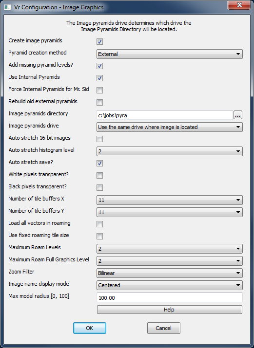
Image Graphics dialog
Image pyramids are used to display zoomed out images whose scales are greater than 1:1. Pyramids are similar to thumbnail images, but there are several images to help with multiple display scales. If the desired scale is between two image pyramids, the higher resolution image pyramid is used.
Image pyramids decrease display time by loading and displaying only the necessary pixels. These files are temporary and may be removed once a project is complete. If "Create Image Pyramids?" is enabled, image pyramids are created when an image without pyramids is opened.
Create image pyramids?
Specifies whether to create image pyramids when an image without them is opened. This parameter should always be checked.
Default: Checked
Pyramid creation method
External - Pyramid files are created externally in the pyramid directory.
Internal - Pyramid files are created internally within the main image.
Image pyramids directory
Defines the directory in which to place image pyramids. The drive letter and path must be included.
Default: C:\jobs\pyra
Image pyramids drive
Specifies the drive on which to place image pyramids. This is useful when using removable drives so the pyramids are not recreated when the drive is moved from one computer to another. Options are:
| • | Use drive specified in Image pyramids directory (above) – Places pyramids in the directory specified by the Image Pyramids Directory field. |
| • | Use the same drive where the image is located – Places pyramids in the directory specified by the Image Pyramids Directory field but defines drive by the location of the source image. For example, if the source image is F:\jobs\images\image1.TIF and the Image Pyramids Directory was C:\jobs\pyra,image pyramids would be stored in the F:\jobs\pyra directory. |
Default: C:\jobs\pyra
Use internal pyramids
Specifies whether to use internal pyramids when they are found inside an image. Disabling "Use internal pyramids" ignores the internal pyramids when images are read.
Force internal pyramids for Mr. Sid
Specifies whether internal pyramids should always be used with Mr. Sid files regardless of the "Use internal pyramids" setting.
Rebuild old external pyramids
Specifies whether to rebuild external pyramid images if the date of the image is older than the image being opened.
Auto stretch 16-bit images?
Specifies whether to perform a histogram stretch (auto levels adjustment) on 16-bit images.
Auto stretch histogram level
Defines image level to use to compute histogram for auto stretching. Higher levels compute faster.
Auto stretch save?
Specifies whether to save levels file after auto stretching.
White pixels transparent?
Black pixels transparent?
Specifies whether to display white/black pixels as transparent. Images often have black or white pixels surrounding the image. This is especially true in the case of rotated images. In most cases, these border pixels are the same color as the window background and are not noticed. These pixels become a problem when images overlap. White and/or black pixels can be displayed as transparent to reveal underlying images through the image border.
Number of tile buffers X / Number of tile buffers Y
Defines number of image tiles to keep in memory in the X and Y direction. This applies to stereo roaming mode only. During roaming, image data loads in multiple tiled sections from disk into a memory cache. The tiles always surround the current cursor location. Each tile is typically the size of the current graphics window.This parameter controls how much image data is buffered at any given time. Raising this number allows roaming a larger area before new image data has to be loaded from disk but also requires more memory, which is a limited resource. The recommend setting is between 3 and 7. The "buffer" command can be used to display a graphical representation of the current tile buffer positions in relation to the current stereo model.
Load all vectors in roaming?
This applies to stereo roaming mode only. If this is turned on, then all vectors are loaded at the current zoom level. Normally this is turned off, and only vectors for the current buffer area are loaded, which is controlled by the Number of tile buffers in the X and Y direction. Turning this on will make initial loading slower, but will allow roaming across the entire file area without pausing again to load vectors. If any problems with low memory are encountered when using this option then it will need to be turned off.
Use fixed roaming tile size?
Specifies whether the internal size of the image cache tiles should match the internal tile size of the images being displayed.This applies to stereo roaming mode only. This is normally disabled, causing the image cache tile size to match the current graphics window size. Disabling this parameter guarantees that the tile buffer will cover enough area to provide clean roaming. Enabling this may parameter may make roaming faster, but if the graphics window is too large then the image display may not always fill the graphics window.
Maximum Roam Levels
Defines the maximum number of zoom levels to keep in memory (quick access cache) in stereo roaming mode. When zooming through different image levels using Page Up/Page Down, the levels that are not currently displayed are kept in memory for fast display the next time they are accessed. If running low on memory (as displayed at the top of the buffer window, which can be turned on with the "buffer" command), set this to 2 or 3. This does not prevent zooming between levels, but causes levels to load a little slower than if they were in the cache.
Maximum Roam Full Graphics Level
Defines the maximum zoom level that should display full graphics in stereo roaming mode. Full graphics displays line fonts and line splining. This is useful for zooming out to view a larger portion of a project while roaming a file with heavy graphics. Turning full graphics off decreases memory usage and increases roaming speed.
NOTE: Level 1 is 1:1 zoom level, level 2 is 1:2 level, level 3 is 1:4 etc.
Zoom Filter
Determines zoom filter mode to use when zooming below 1:1 in stereo roaming graphics.
| • | Nearest Neighbor - Uses nearest neighbor resampling. |
| • | Bilinear - Uses bilinear resampling will be used. This produces a smoother image display. |
Image name display mode
Determines the method with which to display image names in the VrOne graphics window.
| • | Centered - Displays labels in the center of the images. |
| • | Upper Left - Displays labels in the upper left corner of the images. |
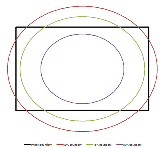
Max Model Radius
Dynamically limits the compilation area in on-the-fly models. The radius is the distance from the center to the corner of the image. The max is a maximum percentage of the radius that will be displayed. The range is from 0 to 100%. The default is 100%. A graphical description of the max radius percentage is given below.
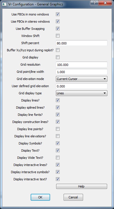
General Graphics dialog
Use FBOs in mono windows
Specifies whether to use Frame Buffer Objects in non-stereo (mono) windows. This is an advanced feature on newer graphics cards that provides cleaner and faster graphics and cursors throughout the Vr Mapping applications. The recommended setting is on, but this may be disregarded if your card has problems using FBOs. Graphics performance may be lessened slightly if this setting is turned off.
Default: On
Use FBOs in stereo windows
Specifies whether to use Frame Buffer Objects in stereo windows. This is an advanced feature on newer graphics cards that provides cleaner and faster graphics and cursors throughout the Vr Mapping applications. The recommended setting is on, but this may be disregarded if your card has problems using FBOs. Graphics performance may be lessened slightly if this setting is turned off.
Default: On
Use Buffer Swapping
Specifies whether to use Buffer Swapping in stereo roaming graphics windows. This is only used when "Use FBOs" is disabled. If "Use FBOs" is off and there are graphics problems, turning buffer swapping offmay fix the problem. Disabling Buffer Swapping may lower roaming speed.
Default: On
Window Shift
Specifies whether to shift the graphics window to center the cursor when the cursor nears the window's edge. This is normally enabled in VrOne for use with an analog or analytical stereo plotting instrument.
Default: Off
Shift percent
Sets the amount by which to shift the graphics window when the arrow keys are used to pan.
Default: 80%.
Buffer Xy/Xyz input during replot?
When "Window Shift" is enabled and the cursor reaches the edge of the window, the window is replotted with the cursor in the center. If there are a lot of graphics to replot, the computer may lose some reads from the input device. If this parameter is checked, input from the stereo plotter is buffered during the replot operation so no reads are lost. This is useful when using applications such as Insert Fly Line (InsFly).
Default: Off
Grid display
Specifies whether to display grid points on the graphics window.
Default: Off
Grid resolution
Defines, in ground units, the resolution at which display the grid points provided "Grid display" is enabled. If the scale of the screen would result in too many grid points displayed, a multiple of the grid resolution will be used but the Grid Resolution parameter will remain unchanged.
Default: 100
Display lines?
Specifies whether to display lines in graphics window. If disabled, neither lines nor splined lines to be displayed.
Default:On
Display splined lines?
Specifies whether to display splined lines in the graphics window. If disabled, splined lines are still displayed, but only the original vertex points are shown. No splining is displayed between them.
Default: Off
Display line fonts?
Specifies whether to display line fonts on the graphics window. If disabled, fonted lines are shown as solid lines.
Default: Off
Display construction lines?
Specifies whether to display construction lines on the graphics window. If disabled, lines with their Construction Flag turned on are not displayed.
Default: On
Display line points?
Specifies whether to display a small cross on each line vertex. This can slow the graphics replotting.
Default: Off
Display line elevations?
Specifies whether to display elevation at each line vertex drawn. This can slow the graphics replotting.
Default: Off
Display symbols?
Specifies whether to display symbols on the graphics window.
Default: On
Display text?
Specifies whether to display text entities on the graphics window.
Default: On
Display interactive lines?
As lines are placed with applications such as Insert Line, the line is shown as a tentative line until it is saved. When points are being digitized, an interactive, tentative line is displayed from the last point digitized to the current cursor position. If this parameter is disabled, this interactive, tentative line segment is not displayed. Disabling is useful on a slower graphics device or one that cannot handle interactive graphics.
Default: On
Display interactive symbols?
When a symbol is being placed or edited, a tentative symbol is displayed. This tentative symbol follows cursor movement during the operations. If this parameter is disabled, this tentative symbol is not displayed. This setting is useful on a slower graphics device or a one that cannot handle interactive graphics.
Default: On
Display interactive text?
When a text entity is being placed or edited, a tentative text entity is displayed. Tentative entities are normally white and may be moved, rotated and scaled without disturbing the existing graphics. If this parameter is disabled, tentative entities are not displayed. This setting is useful on a slower graphics device or one that cannot handle interactive graphics.
Default: On
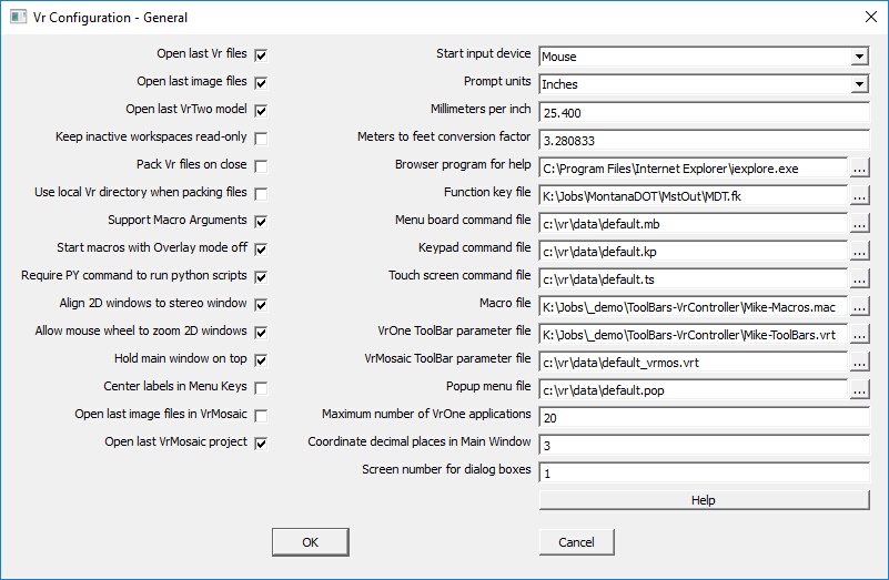
General configuration dialog
Open last VR files
VrOne remembers the VrOne vector files that are open when it ends. Checking "Open Last VR Files" reopens these files when VrOne is started.
Default: On
Open last image files
VrOne remembers the VrOne image files that are open when it ends. Checking "Open Last Image Files" reopens these images when VrOne is started.
Default: On
Open last VrTwo model
VrOne remembers the last VrTwo model open when it ends. Checking "Open Last VrTwo model" reopens the model when VrTwo is started.
Default: On
Keep inactive workspaces read-only?
Specifies whether to keep all open inactive workspaces (.vr files) in read-only mode. This allows other Vr applications to open those workspaces in read-write mode. If disabled, then all open workspaces are kept as read-write and other Vr applications can only open them in read-only mode.
Default: Off
Pack Vr files on close?
Packs Vr files before they are closed.
Default: Off
Use local Vr directory when packing files?
Checking this parameter improves packing speed when working with files over the network.
Default: Off
Support macro arguments
Specifies whether to replace any occurrence of %# (where # represents any number) with the corresponding argument typed in after the macro command. Arguments must be separated by spaces. If an argument contains spaces it must be surrounded by quotes. For example, if a macro named "D" contains the text "DRI %1", and the user types in "D 10", then the command "DRI 10" will be issued.
Default: On
Start macros with Overlay mode off
Specifies whether to run macros with overlay mode off. This ensures that no application will start before the previous one is finished when running Macro commands.
Default: On
Require PY command to run python scripts
Specifies whether to require the PY command to run python scripts. For example, to run a python script named fixlines.py, the command “py fixlines” would be necessary. If this is not on, then the name of the script may be typed to run it, assuming the script name does not match any other built-in command, function key, or macro name. For example, to run fixlines.py, “fixlines” could be entered.
Default: On
Align 2D windows to stereo window
Specifies whether to automatically align 2D windows to match Z rotation of the stereo window. This applies to static and roaming stereo modes.
Default: On
Allow mouse wheel to zoom 2D windows
Allows the mouse wheel to zoom 2D windows. The window is zoomed about the current cursor position. Pressing the SHIFT key while rotating the mouse wheel will center the window at the current cursor location. This option is available with VrOne 2D windows only.
Default: Off
Center labels in Menu Keys
Determines whether to center the button labels in the Menu Keys dialog boxes used by VrOne/VrTwo interactive applications.
Default: On
Open last image files in VrMosaic
VrMosaic remembers the image files that are open when it ends. Checking this option reopens these images when VrMosaic is started.
Default: On
Open last VrMosaic project
Specifies whether to load the last project upon starting VrMosaic.
Default: On
Start input device
Specifies the input device to be used when VrOne first opens. When VrOne starts, it may initialize and start several input devices, but one must be the active device. This parameter is normally used when connected to a stereoplotter. Options for the Start Input Device are:
| • | XY digitizer |
| • | XYZ stereoplotter |
| • | Mouse |
If a device is chosen that is not configured, the Mouse is used as the Start Input Device.
Default: Mouse
Prompt units
Specifies the prompt scale units (millimeters or inches). Each VrOne vector file contains a Target Scale which determines its plotting scale and is used to scale symbols and line fonts. Many size parameters in VrOne are entered in inches or millimeters and are converted to ground units at display time.
Default: Inches
Millimeters per inch
As there are several conversion constants to convert millimeters to inches, VrOne allows this constant to be defined by the user.
Default: 25.4
Meters to feet conversion factor
As there are several conversion constants to convert meters to feet, VrOne allows this constant to be defined by the user.
Default: 3.280833
Browser program for help
Sets the browser to user to view the VrOne help system. The help system in VrOne is based on standard HTML (Hypertext Markup Language).
Default: C:\Program Files\Internet Explorer\iexplore.exe
Function key file
Defines the location of the VrOne Function Key (.fk) file. This file contains VrOne Function keys. Edit Function Key (EdiFun) may be used to edit this file from within VrOne.
Default: C:\vr\data\default.fk
Menu board command file
Defines the location of the VrOne Menu Board Command file. This file contains button assignments for the Menu Board. It is a text file and may be edited. Each button may contain VrOne key-ins, Macros, or Function Keys.
Default: C:\vr\data\default.mb
Keypad command file
This parameter defines the location of the VrOne Keypad Command file. This file contains button assignments for a keypad such as the Keyport 252. It is a text file and may be edited. Each button may contain VrOne key-ins, Macros, or Function Keys.
Default: C:\vr\data\default.kp
Touch screen command file
Defines the location of the Vr Touchscreen command file. This file contains button assignments for the Vr 567 button LCD touch pad. It is a text file and may be edited. It is recommended that the editor provided with the touchscreen be used and that the text file not be edited directly.
Default: C:\vr\data\default.ts
Macro file
Defines the location of the VrOne Macro file. Macros may contain key-ins, other Macros, and/or Function keys. It is a text file and may be edited. It is recommended that the Edit Macro (EdiMac) command be used and with VrOne for editing and that the text file not be edited directly.
Default: C:\vr\data\default.mac
VrOne ToolBar parameter file
Defines the location of the ToolBar parameter file used in VrOne, VrTwo and VrLite. The VrOne ToolBar parameter file name should have a .vrt postfix.
Default: C:\vr\hostdir\vrone.vrt
VrMosaic ToolBar parameter file
Defines the location of the ToolBar parameter file used in VrMosaic. The VrMosaic ToolBar parameter file name should have a .vrt postfix.
Default: C:\vr\hostdir\vrmosaic.vrt
Popup menu file
Defines the location oft he VrLite popup menu file. This file contains the definitions of all popup menu and is edited by the EdiPop command in VrLite.
Maximum number of VrOne applications
VrOne supports Application Overlaying, where multiple mapping applications may be active at the same time. The application at the top is the active application. This parameter sets the maximum number of applications that can be active at a time up to a maximum of 20. When the application stack is full and another application is started, the application at the bottom of the stack is terminated. When an application is terminated for any reason, current data is saved.
Default: 20
Coordinate decimal placed in Main Window
Sets the number of display positions to the right of the decimal point for the XYZ coordinate displayed in the VrOne Main Window. The VrOne data base stores its XYZ positions as double-precision numbers with an accuracy of approximately 14 decimal digits. Setting this parameter does not change the way these numbers are stored in the data base; it simply determines how they are displayed.
Default: 3
Screen number for dialog boxes
There are certain dialog boxes in VrOne that appear in the middle of the screen and do not remember their last position. These are normally temporary information or data entry dialog boxes. Since it is possible to configure Windows to run more than one monitor screen, this parameter sets the screen number on which to display these dialog boxes. The current screen number can be found by Right Clicking on the desktop and choosing Properties then pressing the Settings tab.
Function Key name display mode
Option to display the Function Key name in the Vr Main Window. The options are display the Function Key name or display the Function Key number or both.
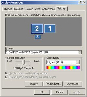
Display Properties dialog from Windows XP
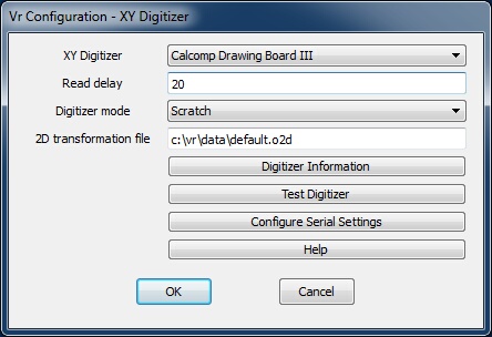
XY Digitizer dialog
XY digitizers are always connected to the VrOne application computer via RS-232 (Serial) interface. Digitizers allow input so VrOne can set up existing map sheets for digitizing. VrOne can also be configured for input to behave similarly to a mouse when in the graphics window.
An advantage to using a digitizer rather than a mouse for editing is function selection from the 12 button keypad on the digitizer puck. This speeds editing by keeping operator typing on the system keyboard to a minimum. Production is also helped by the use of the Vr Menu Board on the digitizing surface allowing for faster menu selections along with Menu Board definitions to suit production needs.
With some digitizer configurations, raw button presses can be cross-referenced to VrOne button presses. For cases where this is supported, an ASCII file with the .key extension is stored in the \vr\hostdir directory. The filename is the device name plus the .key file extension. For example, the key cross-reference file for the Hitachi Puma Plus is puma.key. VrOne commands cannot be mapped to the puck buttons. Only VrOne keys 0-9, *, and # are allowed.
XY Digitizer
Selects an XY digitizer as input to VrOne. Various types of XY digitizers may be chosen.
Default: No XY digitizer
Read delay
On slower computers, the input from the XY digitizer may be too fast for the application. The Read Delay, entered in milliseconds, slows input from of the device by placing a delay between each device read.
Default: 0
Digitizer mode
Specifies the adjustment to perform on raw input from an XY digitizer.
| • | Scratch – Defines a 10”x10” area of the digitizer that is mapped to the graphics screen. Square's origin is the lower left corner of the graphics window. The XY digitizer movements are similar to a mouse, except the cursor has no effect if it is moved from the graphics window. |
| • | Least Squares – Transforms input coordinates to the last orientated map sheet ground coordinates.The Vr program Orient 2D (ori2d) can set up an existing map sheet on an XY digitizer and collect 2D data from the map sheet. This is useful for digitizing existing maps into current databases or for digitizing flight lines from USGS Quadrangle sheets. |
Default: Scratch
2D transformation file
When the Digitizer Mode is set to Least Squares, VrOne looks for a 2D transformation file to convert raw digitizer coordinates to ground coordinates. The Vr program Orient 2D writes this file upon completion of a map sheet orientation. This parameter defines the 2D transformation file name. If multiple map sheets are set up on the same digitizer, this parameter may be changed to match the desired map sheet input.
Default: C:\vr\data\default.o2d
Digitizer Information
Displays the help page with configuration information for supported digitizers.
Test Digitizer
Tests a digitizer to ensure that it is operational. The test may be done after configuration is complete. Pressing this button displays a text window in which raw coordinates are displayed along with digitizer puck button presses.
Configure Serial Settings
All digitizers supported by VrOne use the RS-232 (serial) interface. It may be necessary to change the settings from the defaults if using a non-standard configuration. This may be the case if using the same digitizer for VrOne and another CAD program on the same computer. The most common change is in the COM port. The default COM1 port may be used by another device.
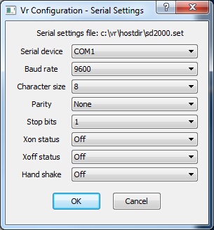
Serial (RS-232) Settings dialog
| • | The Serial device may be set from COM1 to COM9. |
| • | The Baud rate, Character size, Parity and Stop bits are standard serial settings. The digitizer documentation should be consulted for more information about these settings. |
| • | The Xon Status and Xoff status control software flow control between the digitizer and the computer and are normally Off. |
| • | The Hand Shake parameter ensures the input driver performs a bi-directional communication with the input device each read. This parameter is always set to "Off" for XY digitizers. |
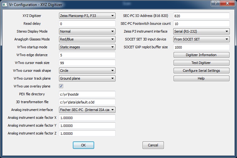
XYZ Digitizer dialog
XYZ digitizers are analog stereo plotters (like the Wild B8), analytical stereo plotters (like the Zeiss P3), and 3D softcopy systems (like VrTwo the SOCET SET).
With some of digitizer configurations, raw button presses can be cross-referenced with VrOne button presses. For configurations where this is supported, an ASCII file with a .key extension is stored in the \vr\hostdir directory. The filename is the device name plus the .key file extension. For example, the key cross-reference file for the Zeiss P1/P2/P3 stereo plotter is p3.key.
XY Digitizer
Sets an XYZ 3D digitizer as input to VrOne. Various types of XYZ digitizers may be chosen.
Default: No XYZ digitizer
Read delay
On slower computers the input from the Xyz digitizer may be too fast for the application. The Read Delay parameter slows input from the device by placing a delay between each device read. This parameter is entered in milliseconds .
Default: 0
Sets the display mode for stereo viewing. "Normal mode" uses the graphics card stereo mode (such as shuttered glasses). "Anaglygh mode" uses different colors for the left and right images.
Default: Normal
Anaglyph Glasses Mode
Controls the colors used for the left and right images provided "Anaglyph mode" is selected as the Stereo display mode. Select the option that matches the type of anaglyph glasses being used. The following options are available:
| • | Red/Blue - Red left eye, blue right eye |
| • | Red/Green - Red left eye, green right eye |
| • | Red/Cyan - Red left eye, cyan right eye |
| • | Blue/Red - Blue left eye, red right eye |
| • | Green/Red - Green left eye, red right eye |
| • | Cyan/Red - Cyan left eye, red right eye |
Default: Red/Blue
VrTwo startup mode
Sets the stereo image viewing mode ("static" or "roaming"). In "Static mode", the images do not move but the cursor does. In "Roaming mode", images move and the cursor stays in the center of the viewing window. Roaming mode is similar to viewing analytical stereo plotting instruments.
Default: Static images
VrTwo edge distance
When VrTwo is in static image mode and the cursor approaches the edge of the graphics window, the stereo image re-centers, placing the cursor in the middle of the window. The Edge Distance parameter sets in pixels the distance from the edge of the window from which the images will be re-centered.
Default: 5 pixels
VrTwo cursor mask size
Cursor Masking example
VrTwo displays two images and the line, symbol and text vectors which make up the stereo softcopy display. When there is a large amount of vector data, the stereo image may become difficult to see. VrTwo offers a Cursor Mask which blanks out the vectors around the cursor so the operator can see the ground clearly. The Cursor Mask may be turned on and off by pressing the Delete key on the system keyboard.
In VrTwo roaming mode, the cursor mask and a magnifier can be toggled. In this mode, vectors are blanked around the cursor and the image is magnified for better pointing ability. In all modes tentative lines that are being placed or edited will display through the cursor mask.
This parameter defines the size of the cursor mask in pixels and has a range of 1-99.
Default: 50
VrTwo cursor mask shape
The VrTwo cursor mask may be displayed as a circle or a square when in roaming mode.
Default: Circle
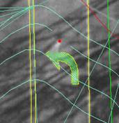
VrTwo cursor track plane
VrTwo has the ability to track the 3D cursor along one of two planes. The View or Model Plane is formed when a stereo pair are formed. The Ground Plane is formed by the ground control system.
For standard aerial photography, where the image plane is almost parallel to the ground, the Ground Plane should always be used. In the case of oblique aerial photography or oblique close range photography, the View Plane can be used for predictable cursor movements. In both modes, the correct XYZ coordinate is always computed for the cursor location. In View Plane, the Z coordinate will change when the cursor is moved from the 3D input device.
Default: Ground Plane
Following is an example of an aerial oblique photo of Mount St. Helens where tracking the View Plane would be useful.
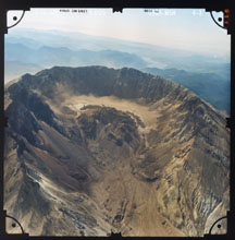
Mount St. Helens, Washington State
VrTwo user overlay plane
If checked, the overlay plane is used in VrTwo stereo to display the cursor and temporary graphics. This parameter typically is the same as the overlay plane setting for the graphics card.
Default: checked
PEX file directory
When VrTwo is interfaced to a Zeiss P1/P2/P3 analytical instrument or an instrument that emulates the Zeiss stereo plotter format, a PEX file is required. The PEX file provides information for the transformation from model to ground and other model information. Orientation programs such as PCAP, AP32 and OriP3 writes this file after model orientation. This parameter sets the directory in which VrOne is to look for a PEX file. VrOne will open the first occurrence of a file with the .PEX extension. Consult orientation program documentation to determine were the program is placing this file.
Default: c:\vr\hostdir
3D transformation file
When VrTwo is interfaced to an analog instrument a 3D Transformation File is needed to convert raw encoder values to ground coordinates. The analog instrument model orientation program Orient 3D (ori3d.exe) will write this file after model orientation. This parameter sets the file name for VrOne to open.
Default: c:\vr\data\default.o3d
Analog instrument interface
When VrTwo is interfaced to an analog instrument there are three interfaces that are supported:
| • | Fischer SEC-PC (Internal ISA card) – This is the original 3-axis stereo plotter card and is not as widely used because of the lack of an ISA slot in newer computers. |
| • | Fischer SEC-232 (External interface) – This interface is an external device that connects to the instrument and connects to the application computer via RS-232 (Serial). It was commonly used when interfacing a UNIX computer to an analog stereo plotter. |
| • | Fischer SEC-PCI (Internal PCI card) – This is the latest card available to interface to an analog instrument and support the widely used PCI interface that is available on most computers. |
Default: Fischer SEC-PC
More information about these interface products may be found on the Fischer Computer Systems web page at http://www.secpc.com/.
Analog instrument scale factor X / Y / Z
When VrTwo is interfaced to an analog instrument, the instrument may have encoders that output different amounts of counts per revolution. The least squares adjustment for analog instruments requires a square input where all three encoders output the same amount of counts.
The amount of counts can be measured from the analog instrument using the 3D Orientation program (or3d). A ruler can be placed on the instrument model motion to measure the axis movement. Normally encoders of different counts will output a significant difference in counts so the measurement does not need to be exact. For example one encoder may output 1000 counts while another may output 5000 counts for the same distance traveled.
The scale factors must be set so that all three axis output the same amount of counts for the same distance traveled. Incorrect settings of the scale factors will make it impossible to set an accurate model.
Default: 1.0
SEC-PC IO Address (816 820)
When using a Fischer SEC-PC interface card to connect to an analog instrument the IO address of the card must be entered. Valid entries are 816 and 820 (decimal). This setting is set on the interface card and the Fisher documentation should be consulted to determine the IO address of the card your using.
Default: 820
SEC-PC Footswitch bounce count
The SEC-PC analog instrument interface comes with a two-pedal footswitch. The hardware does not offer “de-bouncing” so its possible to get several readings from a footswitch press as the switch bounces between on and off. This parameter defines the number of footswitch down readings that must be obtained before it is considered a valid press.
Default: 10
Zeiss P3 instrument interface
The Zeiss P1/P2/P3 analytical stereo plotter instruments support two interface types; RS-232 (Serial) and GPIB (General Purpose Interface Bus). If the GPIB interface is selected then a card must be installed in the application computer. The GPIB interface that VrOne uses is the CEC-488 card from Capitol Equipment Corp (http://www.cec488.com/).
Default: Serial (RS-232)
SOCET SET 3D input device
When VrOne is interfaced to SOCET SET, the 3D input device may be configured and input from SOCET SET or from VrOne. Normally this device is configured on SOCET SET. Configuring it on VrOne will result in a slower read rate as more data is transmitted between VrOne and SOCET SET.
Default: From SOCET SET
SOCET GXP replot buffer size
When VrOne is interfaced to SOCET GXP, this parameter defines the buffer size when plotting all graphics from VrOne.
Default: 1000
Digitizer Information
Pressing this button will display the help page for the supported digitizers. This information will help in the configuration of stereo plotters.
Test Digitizer
After configuring a digitizer, it may be tested here to make sure it is operational before entering VrTwo. Pressing this button displays a text window in which raw coordinates are displayed along with raw stereo plotter button presses.
If testing an analog stereo plotter, a Preset Analog button is available in the text window to allow the initialization of the stereo plotter encoders to preset values. If testing an analytical stereo plotter, a Drive Analytical button is available in the text window which will drive the instrument to the stereo plotter location at the time the test was started. This is to test the drive functionality of the instrument.
Configure Serial Settings
Many of the analytical instruments that are supported by VrOne use the RS-232 (serial) interface. When a digitizer is selected the most commonly used serial settings are automatically selected. However it may be necessary to change these settings if a non-standard configuration is being used. This may be true if the orientation software is using different serial settings than the VrOne defaults. The most common change is in the COM port. The default COM1 port may be used by another device.
Serial (RS-232) Settings dialog
| • | The Serial device may be set from COM1 to COM9. |
| • | The Baud rate, Character size, Parity and Stop bits are standard serial settings and the digitizer documentation should be consulted for more information about these settings. |
| • | The Xon Status and Xoff status control software flow control between the digitizer and the computer and are normally Off. |
| • | The Hand Shake parameter makes sure the input driver performs a bi-directional communication with the input device each read. This parameter being set to Yes is needed with some SD2000 formatted interfaces and is required when driving the instrument. |
Default: Determined by the Xy Digitizer
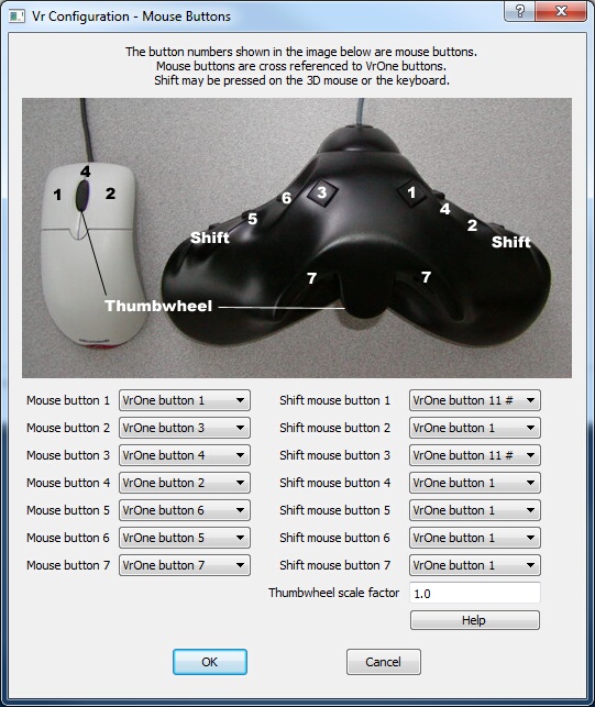
Mouse Buttons dialog
Mouse buttons on the system mouse and the Stealth 3D mouse may be cross-referenced to any of the twelve VrOne buttons (0 through 9, * and #). The original Stealth mouse can be configured with this dialog. This is different from the Stealth Z-Mouse. See the Hardware Configurations help page for more information about the Stealth mice.
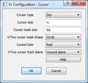
VrTwo Cursor settings dialog
This dialog configures the VrTwo cursor.
Cursor type
This parameter sets the cursor type to Dot or Cross.
Default: Cross
Cursor size
This parameter sets the size of the cursor and is entered as pixels. Fifteen pixels is an adequate size for the cross cursor and four pixels is good for the dot cursor.
Default: 15
VrTwo cursor mask size

VrTwo Cursor Mask example
VrTwo displays two images to and line, symbol and text vectors which make up the stereo softcopy display. At times when there is a large amount of vector data the stereo image may become difficult to see. VrTwo offers a Cursor Mask which blanks out the vectors around the cursor so the operator can see the ground clearly. The Cursor Mask may be turned on and off by pressing the Delete key on the system keyboard.
In VrTwo roaming mode, it is possible to toggle the cursor mask and a magnifier. In this mode, vectors are blanked around the cursor and the image is magnified for better pointing ability. In all modes, tentative lines are displayed through the cursor mask.
This parameter defines the size of the cursor mask in pixels and has a range of 1-99.
Default: 50
VrTwo cursor mask shape
Sets display of the VrTwo cursor mask shape (circle or square) in roaming mode.
Default: Circle
Cursor color
Sets cursor color. Options are white, black, red, green, blue and yellow.
Default: White
VrTwo cursor track plane
VrTwo has the ability to track the 3D cursor along one of two planes: the view (or model) plane and the ground plane. The view plane is formed when a stereo pair is. The Ground Plane is formed by the ground control system.
For standard aerial photography, where the image plane is almost parallel to the ground, the Ground Plane should always be used. In oblique aerial photography or oblique close range photography, the View Plane may be used for predictable cursor movements. In both modes, the correct XYZ coordinate is always computed for the cursor location. In View Plane, the Z coordinate will change when the cursor is moved from the 3D input device.
Default: Ground Plane
The following is an example of an aerial oblique photo of Mount St. Helens where tracking the View Plane would be useful.
Mount St. Helens, Washington State
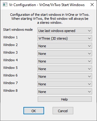
VrOne/VrTwo Start Windows dialog
The graphics windows that created when VrOne or VrTwo start may be configured with VrOne/VrTwo Start Windows. Up to eight graphics windows may be created. 2D VrThree (2D window), 3D VrThree (3D stereo) and 2.5D VrThree (psuedo-3D) windows are supported.
Start windows mode
Defines the parameters to use upon creating graphics windows. "Use last windows opened" copies the parameters from the last open windows. "Use window parameters" follows the parameters listed beside "Window 1-8".
NOTE: When VrTwo starts, the 3D softcopy stereo graphics window will always be opened as Window 1.
Window 1 - Window 8
Defines parameters for new graphics windows if the "Start windows mode" is set to "Use parameters below". Graphic windows options are "VrOne 2D Window", "3D VrThree (3D stereo) or 2.5D "VrThree (pseudo 3D)".
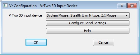
VrTwo 3D Input Device dialog
VrTwo 3D input device
VrTwo supports several types of input devices. These devices are typically hand held controllers that supply the XYZ movement of the floating mark in VrTwo. They also support multiple buttons for digitizing points controlling VrTwo applications. VrTwo can also be operated with the system mouse, in which case the Z is controlled by the wheel. “System Mouse, Stealth U or N type, Z/I Mouse” should be selected.
Options for the 3D Input Type are: System Mouse or Stealth U or N type Mouse, Z/I Mouse, DAT/EM Handwheels, TopoMouse from LH Systems, Stealth Z-Mouse, Stealth Handwheels and Immersion/Stealth E-Mouse
Default: System Mouse, Stealth U or N type, Z/I Mouse
Configure Serial Settings
Many of the 3D input devices that are supported by VrOne use the RS-232 (serial) interface. It may be necessary to change the serial settings from the defaults if you are using a non-standard configuration. The most common change is the COM port. The default COM1 port may be used by another device.
| • | The Serial device may be set from COM1 to COM9. |
| • | The Baud rate, Character size, Parity and Stop bits are standard serial setting. See the 3D input device documentation for more information. |
| • | The Xon and Xoff statuses control software flow between the digitizer and the computer and are normally Off. |
| • | The Hand Shake parameter ensures the input driver performs a bi-directional communication with the input device each read. This parameter is not used for any 3D input device. |
Default: Determined by the current 3D input
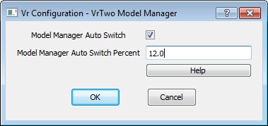
VrTwo Model Manager dialog
Model Manager Auto Switch
If this is on, VrTwo automatically switches between models when the Model Manager window is open. Model switching occurs when mouse approaches the edge of the current model. How close the mouse has to be to the edge is controlled by the Model Manager Auto Switch Percent setting. This setting can be controlled with the AutSwi 0 or AutSwi 1 key-in commands in VrTwo.
Model Manager Auto Switch Percent
Controls the size of the auto switch margin around the model boundary. A smaller percent requires the cursor to be closer to the model edge before switching to the adjoining model. This setting can be controlled with the AutSwi key-in command in VrTwo.
See VrTwo Model Manager for more information.
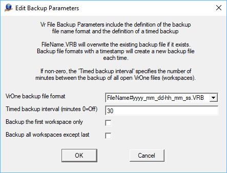
The Edit Backup Parameters dialog
VrOne backup file format - Three backup file name formats are available as follows.
| • | FileName.VRB - The backup file name is the same as the original file except the file extension is .VRB instead of .VR. This option will overwrite the same backup file each time. Example: Original file name: m1703.vr - Backup file name: m1703.VRB |
| • | FileName#yyyy_mm_dd-hh_mm_ss.VRB - The backup file name has a timestamp included which consists of the day and the time. This option will create a new backup file each time. Example: Original file name: m1703.vr - Backup file name: m1703#2019_02_23-11_23_45.VRB where the date is 2/23/2019 and the time is 11:23:45. |
| • | FileName#yyyymmddThhmmss.VRB - The backup file name has a timestamp included which consists of the day and the time. This is similar to the previous timestamp format but is more compact but harder to read. This date/time format conforms to the ISO 8601 date/time format specification. This option will create a new backup file each time. Example: Original file name: m1703.vr - Backup file name: m1703#20190223T112345.VRB where the date is 2/23/2019 and the time is 11:23:45 |
Timed backup interval (minutes 0=off) - A value greater than zero will turn on the automatic backing up of open VrOne file(s). This value is entered as minutes.
Note: If a timestamp VrOne backup file format is selected, the backup of the VrOne files will generate a new files each time a backup is performed. This will occur even if the computer is idle with VrOne, VrTwo, or VrThree running. The user should perform disk maintenance and remove older backup files once they are not needed.
See Backup VrOne File / Backup Parameters for more information.
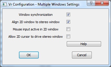
Multiple Windows Settings dialog
Controls window behavior when multiple graphics windows are open. Useful when a 3D stereo window and a 2D graphics window are open.
Window synchronization
When two or more 2D windows are open and this option is checked, a window center operation in one window causes the same window center operation to be performed in all windows. This parameter may be toggled in VrOne/VrTwo with the "Toggle Window Synchronization" (TogSyn)command.
Default: On
Align 2D window to stereo window
Aligns the 2D window rotation to the stereo window rotation. Selecting this option causes the cursor to track in the same X,Y window direction in the stereo window and all 2D windows. This parameter may be toggled in VrTwo with the "Window Align" (WinAli) command.
Default: On
Mouse input active in 2D window
Allows mouse input in the 2D window when the stereo window and one or more 2D windows are open. If enabled, moving the system pointer into a 2D window causes XY cursor movement in all open windows. This parameter may be toggled in VrTwo with the "Toggle Mouse Input From 2D Windows" (Tog2D) command.
Default: Off
Allow 2D cursor to drive the stereo window
Allows XY movement in any open 2D windows to drive the stereo window in the XY direction if the "Mouse input active in 2D window" is active . This parameter may be toggled in VrTwo with the "Toggle Roaming Cursor Drive" (TogRoaCur) command.
Default: Off
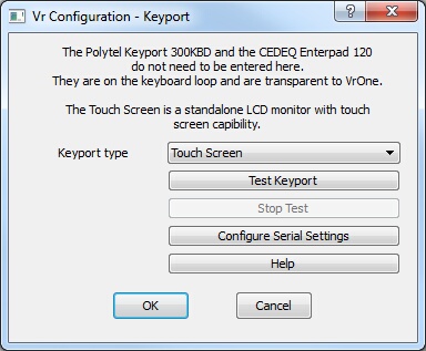
Keyport specification dialog
Keyports are devices that connect to VrOne, giving the user the ability to place commands, macros and/or function keys on buttons for easier program usage.
Keyport type
This parameter defines the current keyport that is interfaced to the computer. Options are:
| • | None – No keyport is connected. All input will come from the system keyboard; |
| • | Polytel Keyport 300 KBD – The Polytel Keyport 300, connected in the keyboard loop; |
| • | Polytel Keyport 300 Serial – The Polytel Keyport 300, connected to the application computer through an external RS-232 (Serial) interface; |
| • | CEDEQ Enterpad 120 – The CEDEQ Enterpad 120, a keypad connected in the keyboard loop; |
| • | Keyport 252 USB or Serial – The DAT/EM Keyport, connected through the USB or Serial interface. It is recommended to use the Serial interface only. |
| • | Vr Touchscreen – The Vr Touchscreen offers 567 buttons in a 7-inch form factor. This is an LCD touch screen with dynamic menus. It is configured as another screen in Windows. |
Test Keyport
Tests the current keyport by displaying button presses in a text window.
Stop Test
Stops a keyport test in progress.
Configure Serial Settings
Several supported keyports are connected via RS-232 (Serial) interface. It may be necessary to change the serial settings if you are using a non-standard configuration. The most common change is in the COM port. The default COM1 port may be used by another device.
Serial (RS-232) Settings dialog
| • | The Serial device may be set from COM1 to COM9 |
| • | The Baud rate, Character size, Parity and Stop bits are standard serial settings. Consult keyport documentation for more information. |
| • | The Xon and Xoff statuses control software flow between the keyport and the computer and are normally Off. |
| • | The Hand Shake parameter makes sure the input driver performs a bi-directional communication with the input device each read. This parameter is always set to Off for the Keyport configuration. |
Default: Determined by the Keyport Type
NOTE: The VrController touchscreen is not included in this documentation since it does not require configuration.
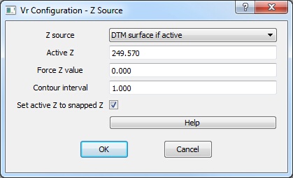
Z Source dialog
Z Source
There are several possible sources for the Z axis.
| • | XYZ digitizer or Active Z – If the current input device is capable of inputting Z, that value is used. If the current input device cannot input Z, the Active Z is used. The active Z can be set at any time with one of the Z management commands. |
| • | DTM surface if active – If a DTM surface is active, the elevation is interpolated from the DTM surface based on the current XY position |
| • | Force Z – Forces Z to a constant value |
Force Z value
Defines an elevation to be used as the Z input if "Force Z" is enabled.
Contour interval
Defines, in ground units, the contour interval to be used by several Z management commands (such as Z +, which adds the contour interval to the current elevation).
Set active Z to snapped Z?
Sets the Active Z to the elevation of the snapped point. This is useful to label symbol X’s with their elevations in VrOne when an XY digitizer or mouse is the active input device.
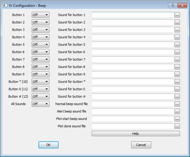
Beep configuration dialog
Sets sounds for each of the twelve VrOne buttons and for other VrOne actions. Any wave sound file (.wav) may be played when a button is pressed or an action occurs.
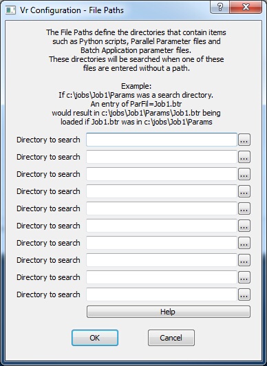
File Paths definition dialog
File Paths define the directories that contain items like Python scripts, Parallel Line parameter files and Batch Application parameter files. These File Path directories will be searched when one of these files isentered without a path.
For example:
If C:\jobs\Job1\Params was a search directory and an entry of ParFil=Job1.btr was entered in a Macro. This would result in c:\jobs\Job1\Params\Job1.btr being loaded if Job1.btr was in the c:\jobs\Job1\Params directory.

NumLock Control dialog
The NumLock Control conditions the system keyboard Number Lock depending on the status of the VrOne Application Stack. Using NumLock Control helps use the system keyboard keypad as a method to start VrOne commands and press one of the twelve VrOne buttons instead of using the F1-F12 buttons at the top of the keyboard.
Control NumLock?
| • | Checked – NumLock is turned off if there are any applications on the stack. NumLock is turned on if there are no applications on the stack. When NumLock is off, the keyboard keypad may be used as VrOne buttons 0-9, * and #. |
| • | Not checked – NumLock is not changed. |
Default: Off
Use asterisk on keypad?
| • | Checked – The asterisk key on the keypad is used for VrOne button *. |
| • | Not checked – The period key is used from VrOne button *. |
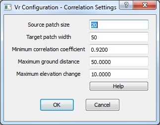
Correlation Settings dialog
The Correlation Settings are used with the VrOne application Correlate Area (CorAre). See Correlate Area for more information.
Source patch size
Sets the size in pixelsof the smaller source patch of pixels to be iterated through the Target Patch. The Source Patch is from one photo, normally the left, and the Target Patch from the other, normally the right. The Source Patch Size should be an even multiple of the Target Patch width. .
Default: 20
Target patch width
The Target Patch Size sets the width in pixels of the larger target patch of pixels through which the Source Patch iterates. The Source Patch is from one photo, normally the left, and the Target Patch from the other photo, normally the right. The Source Patch Size should be an even multiple of the Target Patch.
Minimum correlation coefficient
The result of a correlation is the Correlation Coefficient. A Coefficient of 1.0 indicates a perfect match, while values less than 0.9 indicate a less desirable result. It is recommended that and values below 0.6 be rejected. This parameter is the minimum acceptable correlation result. This parameter is entered as a reasonable coefficient value from 0.50 to 0.99.
Default: 0.92
Maximum ground distance
Specifies the value in ground units which cannot be exceeded by the XY distance of a new correlated point from the last accepted point.
Default: 50
Maximum elevation change
Specifies the value in ground units which cannot be exceed by the elevation distance of a new correlated point from the last accepted point.
Default: 10
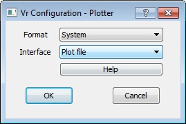
Plotter dialog
Sets the parameters for plotting to hard copy devices. See the VrOne command Plot (Plo) for more information about plotting.
Format
Several plot formats are supported.
| • | HP-GL – Basic Hewlett Packard Graphics Language. This is used to plot vectors. |
| • | HP-GL/2 – Hewlett Packard Graphics Language 2. This is a compressed version of HP-GL and is used to plot vectors. |
| • | Hp-GL/2 and HP RTL – Hewlett Packard Graphics Language 2 and Hewlett Packard Raster Transfer Language. These two formats are combined into one plot file and enable plotting vectors over images. This format may also be used when plotting vectors without images or images without vectors. |
| • | Postscript – Basic Adobe Postscript format. This format is used by many publishers. |
Default: HP-GL/2 and HP RTL
Interface
The Interface parameter defines the interface to the plotter.
| • | Plot file – Writes the contents of the plot to a plot file which can then be transferred to the plotter |
| • | RS-232 – The computer is connected to the plotter via RS-232 (Serial) cable. This is an interface for older line plotters only. It is no longer supported. |
Default: Plot file
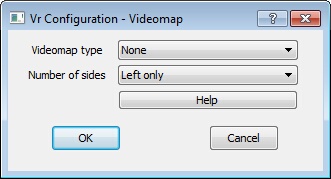
Zeiss Videomap dialog
VrOne supports the Zeiss Videomap 2 and the Zeiss Videomap 30 vector super-imposition systems on the Zeiss P1/P2/P3 analytical instruments.
Videomap type
Defines the Videomap type. Options are None, Videomap 2, Videomap 30 and Test.
Default: None
Number of sides
Videomap is normally imposed on the left image. However, it is possible to have two Videomap units for the left and right sides when using a Zeiss P1. Options for this parameter are Left only and Stereo.
Default: Left only